
Nondestructive testing system and nondestructive testing method based on pseudo-random coding

A pseudo-random coding and non-destructive testing technology, applied in the field of non-destructive testing, can solve the problems of detection signal attenuation, influence of coil impedance, difficulty in ensuring effective work, etc., and achieve the effect of maintaining stability, detection accuracy and accuracy improvement

Pending Publication Date: 2021-03-12
CHINA RAILWAY CONSTR HEAVY IND
View PDF3 Cites 0 Cited by
  • Summary
  • Abstract
  • Description
  • Claims
  • Application Information

AI Technical Summary

Problems solved by technology

However, the impact signal generated by the transducer lacks the suppression effect on noise interference, and it is difficult to ensure effective work in a strong interference environment
[0009] There are also some studies that reduce the eddy current growing in the magnet by adding a specific conductive material, so as to weaken the sound wave generated on it, reduce the generation of noise, and improve the signal-to-noise ratio of the echo signal. Eddy currents are generated in the material, this method affects the coil impedance
In addition, in the detection of multiple defects in steel strands using rare earth giant magnetostrictive transducers, the use of detection signals of different frequencies for steel strands under different load stresses has achieved certain results; Frequency Conversion Control of Giant Magnetostrictive Transducer
Furthermore, in the application of non-destructive testing, there is no good solution to the problem that the detection signal is continuously attenuated with the detection length during the pipeline and cable detection process.

Method used


Image

  • Nondestructive testing system and nondestructive testing method based on pseudo-random coding
  • Nondestructive testing system and nondestructive testing method based on pseudo-random coding
  • Nondestructive testing system and nondestructive testing method based on pseudo-random coding

Examples


Embodiment

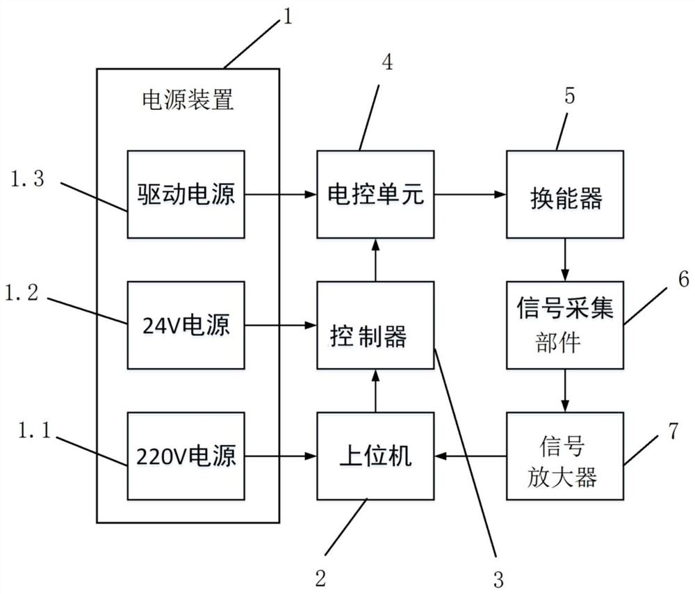
[0038] A non-destructive testing system based on pseudo-random codes, see figure 1 , including a power supply unit 1, a host computer 2, a controller 3, an electric control unit 4, a transducer 5 and a signal acquisition component 6, and the host computer 2, the controller 3 and the electronic control unit 4 are all connected with the power supply unit 1 Electrical connections, details are as follows:

[0039] The power supply device 1 includes a 220V power supply 1.1, a 24V power supply 1.2 and a drive power supply 1.3, the 220V power supply 1.1 is electrically connected to the upper computer 2, and supplies power to the upper computer; the 24V power supply 1.2 is electrically connected to the controller 3, and provides power to the controller. Power supply: the drive power supply 1.3 is electrically connected to the electronic control unit 4 to supply power to the electronic control unit.

[0040]The upper computer 2 includes a shift register that can generate a pseudo-rand...


PUM


Abstract

The invention discloses a nondestructive testing system based on pseudo-random coding. The system comprises a power supply device, an upper computer, a controller, an electric control unit, a transducer and a signal acquisition part; the upper computer outputs a pseudo-random coding sequence; the controller decodes the pseudo-random coding sequence into pulses and outputs a pulse sequence; the electric control unit receives the pulse sequence and then outputs a voltage or current signal to the transducer to obtain a controllable transducer; the signal acquisition part records the impact timesand frequency and feeds back to the upper computer; and the upper computer processes the impact times and frequency. According to the scheme of the invention, pseudo-random sequence impact is realizedby combining pseudo-random sequence programming control, noise and interference are suppressed to the greatest extent, and accurate identification and extraction of effective signals are ensured; andby means of electronic pulse sweep frequency impact, single impact energy is superposed, and the nondestructive testing distance and precision are improved. The invention further discloses a nondestructive testing method which adopts the nondestructive testing system based on pseudo-random coding and can be applied to the field of nondestructive testing of bridges and concrete structures.

Description

technical field [0001] The invention relates to the technical field of non-destructive testing, in particular to a pseudo-random code-based non-destructive testing system and a non-destructive testing method. Background technique [0002] The giant magnetostrictive transducer is a device that converts electromagnetic energy into mechanical energy or acoustic energy, and has high electromechanical conversion efficiency. As the source of acoustic nondestructive testing, the giant magnetostrictive transducer has the advantages of good repeatability and convenient acquisition of multiple sets of signals compared with the hammer source. [0003] Compared with piezoelectric transducers, the excited ultrasonic energy is higher, which is suitable for acoustic nondestructive testing of the quality of large-volume components in engineering. Due to the low energy density and poor thermal conductivity of piezoelectric ceramic materials, when working under continuous and high-power cond...

Claims


Application Information

Patent Timeline
Patent Type & Authority Applications(China)
IPC IPC(8): G01N29/04G01N29/24
CPCG01N29/045G01N29/2437G01N2291/0232
Inventor 廖金军王肖蒋海华苏亮易达云徐震曹龙飞伍容
Owner CHINA RAILWAY CONSTR HEAVY IND
Learn More