Automatic welding production line of automobile floor
An automatic welding and production line technology, applied in welding equipment, welding equipment, auxiliary welding equipment, etc., can solve the problems of chip ejection, difficulty in collection, time-consuming and labor-intensive efficiency, etc., to achieve increased accuracy, time-saving and labor-saving efficiency, and easy positioning Effect
- Summary
- Abstract
- Description
- Claims
- Application Information
AI Technical Summary
Problems solved by technology
Method used
Image
Examples
Embodiment 1
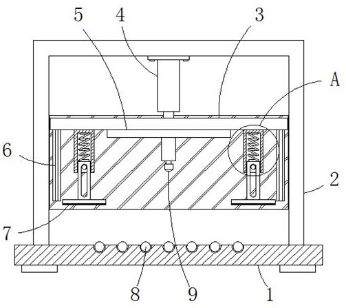
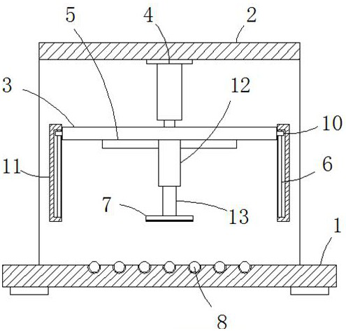
[0026] Example 1 as Figure 1-3 As shown, this kind of cold chain logistics distribution equipment includes a base 1, the upper end of the base 1 is fixedly connected with a U-shaped plate 2, and the inside of the U-shaped plate 2 is provided with a horizontal movable plate 3, and the center of the lower end of the horizontal part of the U-shaped plate 2 A hydraulic rod 4 is fixed at the center, and the end of the piston rod of the hydraulic rod 4 is fixedly connected with the center of the upper end of the movable plate 3. The lower end of the movable plate 3 is fixedly provided with a welding device 9 through the moving mechanism 5, and the left and right sides of the lower end of the movable plate 3 Both are fixedly connected with fixed sleeves 12, and the interior of the two fixed sleeves 12 is fixedly provided with a pressing mechanism, and the front and rear sides of the movable plate 3 are all provided with vertical baffles 11, and the opposite sides of the two baffles 1...
Embodiment 2
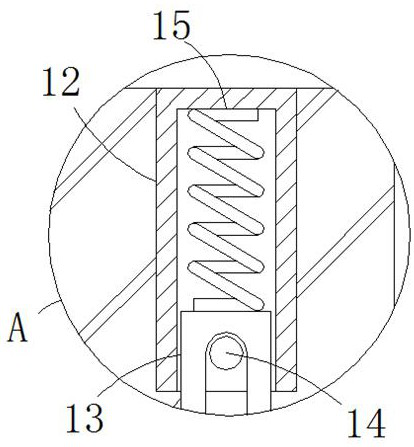
[0027] Embodiment 2 is on the basis of embodiment 1 such as image 3 As shown, its abutting mechanism comprises movable rod 13, spring 15, stopper rod 14 and pressure plate 7, and the rod wall of movable rod 13 is slidably connected with the inner cylinder wall of fixed sleeve 12, and the lower end of movable rod 13 extends to The outside of the fixed sleeve 12, the pressure plate 7 is horizontally fixedly arranged on the lower end of the movable rod 13 and fixedly connected, the front side rod wall of the movable rod 13 is provided with a bar-shaped hole, and the limit rod 14 is longitudinally arranged in the inside of the bar-shaped hole, and the limit The front and rear ends of the position rod 14 all extend to the outside of the strip hole and are fixedly connected with the lower inner wall of the fixed sleeve 12, and the two ends of the spring 15 are connected with the inner wall of the fixed sleeve 12 and the inner wall of the movable rod 13 respectively. The upper end i...
Embodiment 3
[0028] Embodiment 3 is such as on the basis of embodiment 1 figure 2 As shown, its sliding mechanism includes a slide block 10 and a slide bar 6, the slide bar 6 is vertically fixedly arranged in the inside of the bar groove, the slide block 10 is slidingly socketed with the upper side of the bar wall of the slide bar 6, and the slide bar 10 The side wall on one side near the hydraulic rod 4 extends to the outside of the strip groove and is fixedly connected with the movable plate 3 .
PUM
 Abstract
Description
Claims
Application Information
 - R&D
- Intellectual Property
- Life Sciences
- Materials
- Tech Scout
- Unparalleled Data Quality
- Higher Quality Content
- 60% Fewer Hallucinations
Browse by: Latest US Patents, China's latest patents, Technical Efficacy Thesaurus, Application Domain, Technology Topic, Popular Technical Reports.
© 2025 PatSnap. All rights reserved.Legal|Privacy policy|Modern Slavery Act Transparency Statement|Sitemap|About US| Contact US: help@patsnap.com


