Pyrolysis device for waste plastic oil-production processing

A technology for waste plastics and oil production, which is applied in the petroleum industry, processing hydrocarbon oil, preparation of liquid hydrocarbon mixtures, etc., and can solve problems such as poor pyrolysis efficiency of plastic raw materials.

Inactive Publication Date: 2021-03-16
王培培
View PDF0 Cites 2 Cited by
  • Summary
  • Abstract
  • Description
  • Claims
  • Application Information

AI Technical Summary

Problems solved by technology

[0004] Based on the technical problem of poor pyrolysis efficiency of plastic raw materials in t...

Method used


Image

  • Pyrolysis device for waste plastic oil-production processing
  • Pyrolysis device for waste plastic oil-production processing
  • Pyrolysis device for waste plastic oil-production processing

Examples


Embodiment 1

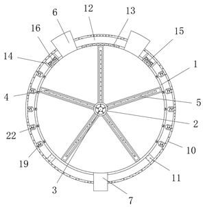
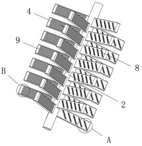
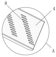
[0030] refer to Figure 1-4 , a pyrolysis device for processing waste plastics into oil, comprising a pyrolysis tank 1, the pyrolysis tank 1 is arranged in a horizontally placed cylindrical structure, and both ends of the pyrolysis tank 1 are provided with sealing covers, and the thermal The middle position between the inner walls of the two ends of the pyrolysis tank 1 is rotatably connected with a fixed pipe 2, and one end of the fixed pipe 2 is connected with a drive motor, and the inner wall of the end of the pyrolysis tank 1 away from the drive motor is fixed at a position corresponding to the fixed pipe 2. A heating element 3, the outer wall of the fixed pipe 2 is fixed with a plurality of dispersing elements 4, and the inside of the dispersing element 4 is provided with a mounting groove, the inner wall of the mounting groove is fixed with a second heating element 5, and the top two of the outer wall of the pyrolysis tank 1 are A feed pipe 6 is fixed on both sides, and ...

Embodiment 2

[0035] refer to Figure 1-6 , a pyrolysis device for waste plastic oil processing, a plurality of fixed cylinders 17 are fixed on both sides of the inner wall of the thermal insulation shell 10, and the end of the fixed cylinder 17 away from the thermal insulation shell 10 and the outer wall of the pyrolysis tank 1 There is a gap between them, the end of the inner wall of the fixed cylinder 17 close to the pyrolysis tank 1 is slidably connected with a hemispherical block 19, and the end of the block 19 away from the pyrolysis tank 1 is connected with the inner wall of the heat preservation shell 10. A spring 18, a chute 20 is provided at the position corresponding to the inner wall of the pyrolysis tank 1 and the block 19, and the inner wall of the chute 20 is slidably connected with a dispersing block 22, and one end of the dispersing block 22 is connected to the inner wall of the chute 20 There is a second spring 21, and the end of the dispersion block 22 away from the pyrol...


PUM


Abstract

The invention belongs to the technical field of waste plastic-to-oil processing, particularly relates to a pyrolysis device for waste plastic oil-production processing, and provides the following scheme aiming at the problem of poor pyrolysis efficiency of plastic raw materials in the prior art: the pyrolysis device comprises a pyrolysis tank, the pyrolysis tank is arranged to be of a horizontally-placed cylindrical structure, sealing cover plates are arranged at the two ends of the pyrolysis tank, a fixing pipe is rotatably connected to the middle position between the inner walls of the two ends of the pyrolysis tank, one end of the fixing pipe is in transmission connection with a driving motor, a first heating piece is fixed to the position, corresponding to the fixing pipe, of the innerwall of the end, away from the driving motor, of the pyrolysis tank, and a plurality of dispersing pieces are fixed to the outer wall of the fixing pipe. The plastic is heated and dissolved at all positions in the pyrolysis tank, the pyrolysis efficiency is prevented from being affected by single-point heating, plastic raw materials in the pyrolysis tank are dispersed in cooperation with the dispersion piece and the dispersion strips on the dispersion piece, and the situation that heat conduction heat is difficult to diffuse due to accumulation is avoided.

Description

technical field [0001] The invention relates to the technical field of waste plastic to oil processing, in particular to a pyrolysis device for waste plastic to oil processing. Background technique [0002] Plastic is a high molecular compound polymerized by addition polymerization or polycondensation reaction with monomer as raw material. It has medium resistance to deformation and is between fiber and rubber. Composed of additives such as additives and colorants, plastics are important organic synthetic polymer materials and are widely used. However, the "white pollution" caused by waste plastics is becoming more and more serious, so the treatment of waste plastics is becoming more and more important. [0003] Utilizing waste plastics for oil-making treatment is a treatment process developed in recent years. Nowadays, in the process of waste plastics oil-making treatment process, the plastic raw materials are generally crushed, and the plastic raw materials are melted by h...

Claims


Application Information

Patent Timeline
IPC IPC(8): C10G1/10B01D46/24B01D46/10
CPCB01D46/10B01D46/2411C10G1/002C10G1/10C10G2300/1003
Inventor 王培培
Owner 王培培
Why Eureka
Try Eureka