Supercharge Your Innovation With Domain-Expert AI Agents!

Processing system for building outer wall heat insulation wall surface structure construction

A technology for thermal insulation and building exterior walls, applied in building components, building structures, buildings, etc., can solve problems such as easy leakage of spray, cumbersome manual application, and reduce the production efficiency of exterior wall insulation walls, so as to avoid leakage. Glue area, the effect of improving production efficiency

Active Publication Date: 2021-03-16
中海建筑有限公司
View PDF9 Cites 4 Cited by
  • Summary
  • Abstract
  • Description
  • Claims
  • Application Information

AI Technical Summary

Problems solved by technology

[0004] (1) When manually applying glue between the exterior wall surface and the steel wire mesh, the glue is usually applied manually between the exterior wall and the steel mesh. During the manual application process, it is difficult to manually apply the glue to the high position on the exterior wall surface. It needs to be assisted by scaffolding and other equipment, which makes manual application cumbersome and reduces the production efficiency of external wall insulation walls;
[0005] (2) Existing building exterior wall insulation wall surface production equipment usually sprays glue on the building exterior wall and steel wire mesh directly through the existing building exterior wall insulation wall surface production equipment when making the insulation wall surface of the building exterior wall During the spraying process, the amount of glue sprayed by glue spraying is less, and the spraying area is prone to leaks during the spraying process, resulting in weak bonding between the steel mesh and the surface of the outer wall

Method used


Image

  • Processing system for building outer wall heat insulation wall surface structure construction
  • Processing system for building outer wall heat insulation wall surface structure construction
  • Processing system for building outer wall heat insulation wall surface structure construction

Examples


Embodiment Construction

[0033] In order to make the technical means realized by the present invention, creative features, goals and effects easy to understand, the following combination figure 1 to Figure 8 , to further elaborate the present invention.

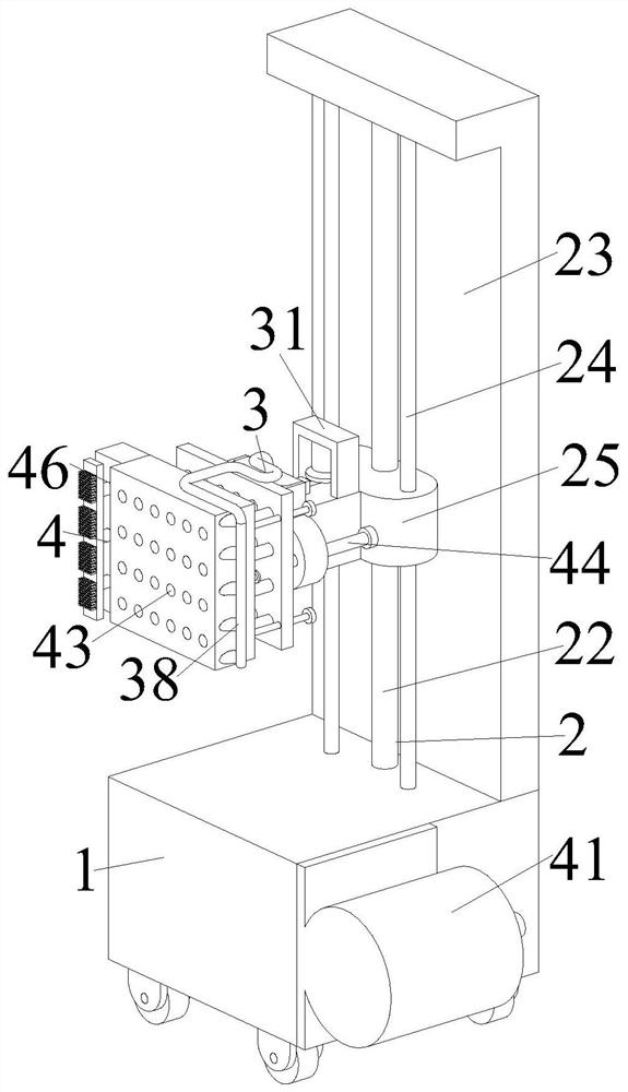
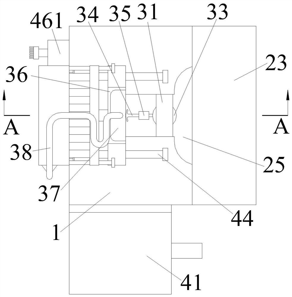
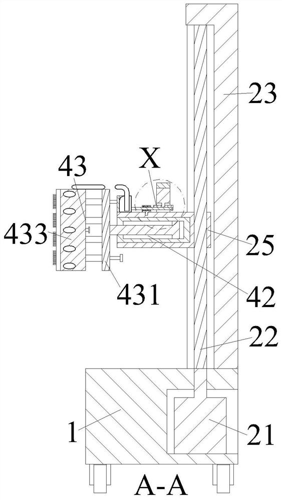
[0034] A processing system for building exterior wall thermal insulation wall structure construction, comprising a mounting plate 1, a driving device 2, a gluing device 3 and a gluing device 4, the upper end of the mounting plate 1 is equipped with a driving device 2, and the driving device 2 A gluing device 3 is installed on the upper side, and a gluing device 4 is installed on the left side of the gluing device 3, and the gluing device 4 is installed on the left side of the driving device 2; wherein:

[0035] The drive device 2 includes a rotary motor 21 installed on the right side of the mounting plate 1. The output end of the rotary motor 21 is equipped with a threaded rod 22. The upper end of the threaded rod 22 is installed on the upper end of...


PUM


Abstract

The invention relates to a processing system for building outer wall heat insulation wall surface structure construction. The system comprises a mounting plate, a driving device, a gluing device and agumming device, the driving device is mounted at the upper end of the mounting plate, the gluing device is mounted on the upper side of the driving device, the gumming device is mounted on the left side of the gluing device, and the gumming device is mounted on the left side of the driving device. The problems that when a glue is manually smeared, the glue is directly smeared between an outer wall and a steel wire net, auxiliary smearing needs to be conducted on the high position through a scaffold, so that manual smearing is tedious, the manufacturing efficiency of an outer wall heat preservation wall surface is reduced, when existing building outer wall heat preservation wall surface production equipment conducts producing, the glue is directly sprayed between the building outer wall and the steel wire net, in the spraying process, the glue output amount of glue spraying is small, a spraying missing area is prone to being generated in the spraying process, and therefore bonding between the steel wire net and the surface of the outer wall is not firm are solved.

Description

technical field [0001] The invention relates to the technical field of building exterior walls, in particular to a processing system for building exterior wall thermal insulation wall structure construction. Background technique [0002] The thermal insulation wall is a kind of "wall" that plays a role in thermal insulation of the wall. Usually, steel wire mesh is laid on the surface of the wall. The "wall surface" of thermal insulation, the thermal insulation external wall prevents the external wall of the building from being damaged due to the change of temperature difference, and then threatens the safety of the residents in the building. The thermal insulation external wall has a protective effect on the main structure and buffers the temperature Changes lead to stress caused by structural deformation. When making the thermal insulation exterior wall, it is necessary to apply glue between the building exterior wall and the steel mesh after the steel mesh is laid to ensur...

Claims


Application Information

Patent Timeline
IPC IPC(8): E04F21/08E04B1/76
CPCE04F21/08E04B1/7625Y02B30/90
Inventor 成艳秋
Owner 中海建筑有限公司
Features
  • R&D
  • Intellectual Property
  • Life Sciences
  • Materials
  • Tech Scout
  • Unparalleled Data Quality
  • Higher Quality Content
  • 60% Fewer Hallucinations
Learn More