Construction method of super-large-diameter anchoring body

A technology with super large diameter and construction method, which is applied in earthwork drilling, installation of bolts, mining equipment, etc., can solve the problems of insufficient bearing capacity of anchor cables, complex structure, and unclean cleaning of soil and slag in the hole, so as to reduce the hole wall. The effect of collapse risk, flexible processing and simple structure

Pending Publication Date: 2021-03-16
厦门能巧堂建筑工程有限公司
View PDF9 Cites 0 Cited by
  • Summary
  • Abstract
  • Description
  • Claims
  • Application Information

AI Technical Summary

Problems solved by technology

[0003] At present, some reaming drill bits are used to form holes in larger-diameter anchors, and their structures are more complicated, and they need to be configured separately.
It is also prone to the problem of hole wall collapse caused by unclean cleaning of soil slag in the hole and unbalanced soil pressure on the hole wall when large-diameter holes are formed, which affects the strength and integrity control indicators of the anchoring body, often resulting in engineering accidents with insufficient anchor cable bearing capacity

Method used


Image

  • Construction method of super-large-diameter anchoring body
  • Construction method of super-large-diameter anchoring body
  • Construction method of super-large-diameter anchoring body

Examples


Embodiment 1

[0033] see Figure 1-5 , the present invention provides the following technical solutions: a construction method for super-large-diameter anchors, comprising the following steps:

[0034] S1. The symmetrical steel plate of the casing boot is protruded out;

[0035] S2, rotary soil cutting drilling;

[0036] S3, casing follow-up;

[0037] S4, high pressure water reverse slag;

[0038] S5, super large diameter hole forming;

[0039] S6. Manufacture and installation of anchor rod body;

[0040] S7. Grouting for full length hole section;

[0041] S8, super large diameter anchor body is formed.

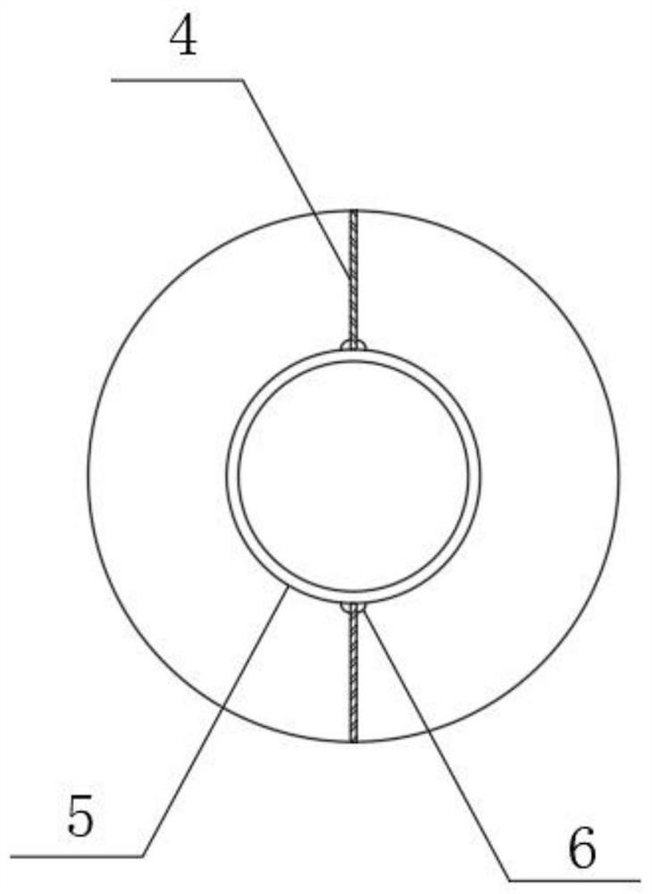
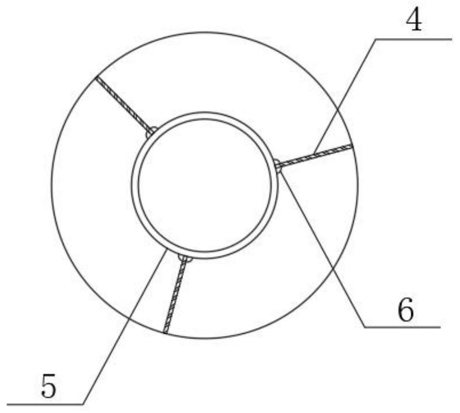
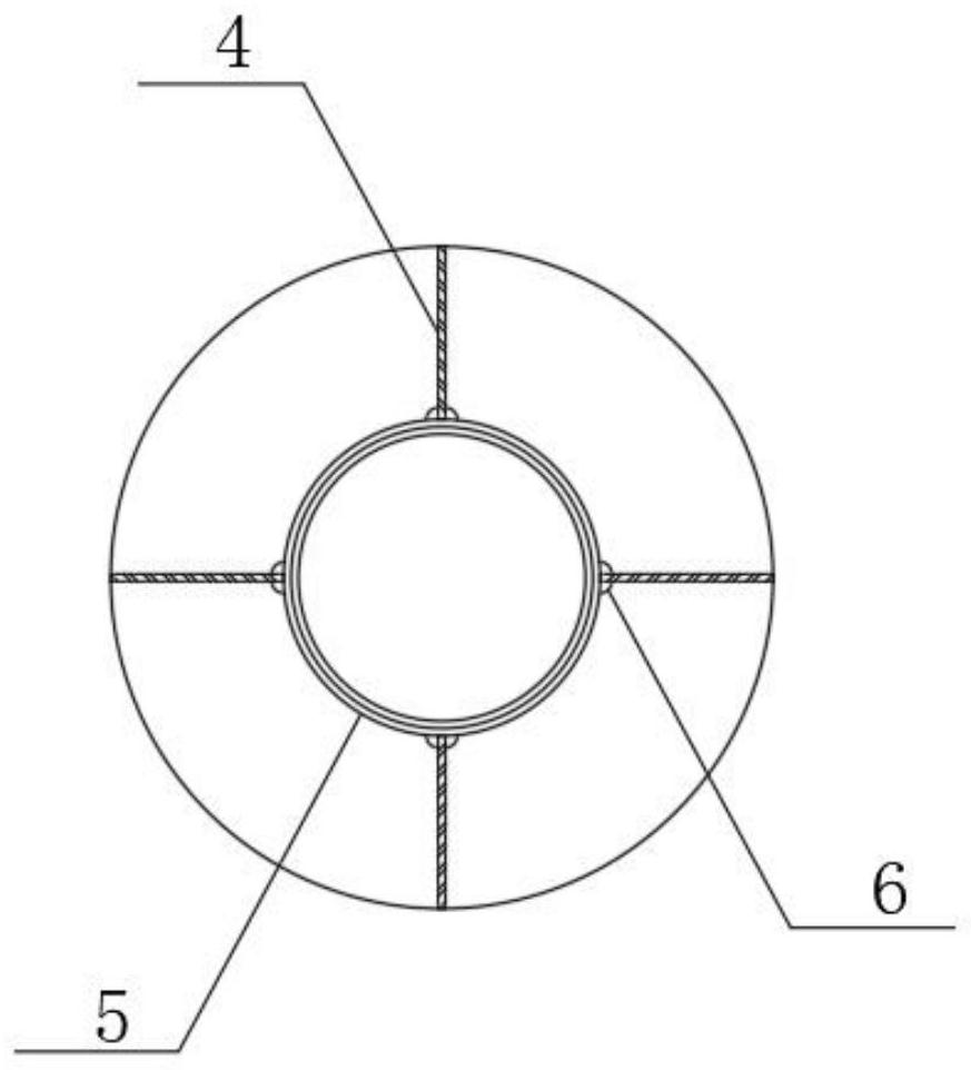
[0042] Specifically, in step S1, the casing shoe 1 produced by the symmetrical steel plate protruding is installed on the front end of the casing 2, the steel plate 4 is flush and symmetrically welded with the casing shoe 3 with the axis of the casing 2 as the center line, and the casing 2 is pulled by the motor Rotate, the steel plate 4 is rotated to cut the soil, the hole is clear...

Embodiment 2

[0050] see Figure 1-5 , the present invention provides the following technical solutions: a construction method for super-large-diameter anchors, comprising the following steps:

[0051] S1. The symmetrical steel plate of the casing boot is protruded out;

[0052] S2, rotary soil cutting drilling;

[0053] S3, casing follow-up;

[0054] S4, high pressure water reverse slag;

[0055] S5, super large diameter hole forming;

[0056] S6. Manufacture and installation of anchor rod body;

[0057] S7. Grouting for full length hole section;

[0058] S8, super large diameter anchor body is formed.

[0059] Specifically, in step S1, the casing shoe 1 produced by the symmetrical steel plate protruding is installed on the front end of the casing 2, the steel plate 4 is flush and symmetrically welded with the casing shoe 3 with the axis of the casing 2 as the center line, and the casing 2 is pulled by the motor Rotate, the steel plate 4 is rotated to cut the soil, the hole is clear...

Embodiment 3

[0067] see Figure 1-5 , the present invention provides the following technical solutions: a construction method for super-large-diameter anchors, comprising the following steps:

[0068] S1. The symmetrical steel plate of the casing boot is protruded out;

[0069] S2, rotary soil cutting drilling;

[0070] S3, casing follow-up;

[0071] S4, high pressure water reverse slag;

[0072] S5, super large diameter hole forming;

[0073] S6. Manufacture and installation of anchor rod body;

[0074] S7. Grouting for full length hole section;

[0075] S8, super large diameter anchor body is formed.

[0076] Specifically, in step S1, the casing shoe 1 produced by the symmetrical steel plate protruding is installed on the front end of the casing 2, the steel plate 4 is flush and symmetrically welded with the casing shoe 3 with the axis of the casing 2 as the center line, and the casing 2 is pulled by the motor Rotate, the steel plate 4 is rotated to cut the soil, the hole is cleared...


PUM


Abstract

The invention belongs to the technical field of geotechnical engineering anchoring, and particularly relates to a construction method of a super-large-diameter anchoring body. The construction methodcomprises the following steps of S1, manufacturing symmetrical steel plates of a casing shoe in an extending manner; S2, performing rotary soil cutting and drilling; S3, performing casing pipe following; S4, performing high-pressure water slag returning; S5, forming a hole with an ultra-large diameter; S6, manufacturing and mounting an anchor rod body; S7, grouting a full-length hole section; andS8, forming the super-large-diameter anchoring body. The steel plates are symmetrically arranged on a conventional casing shoe on the market in an extending manner, the structure is simple, the lengthof the steel plates is determined according to the reaming diameter, machining and manufacturing are flexible and convenient, soil is cut into slag under high-speed rotation of the extending steel plates, and ultra-large-diameter reaming is completed in a soil body outside the casing shoe range; the soil cut into the slag by the steel plates is effectively and thoroughly cleaned out of the hole through pipe-following drilling and high-pressure water slag returning, action of the pressure water exists between the wall of a casing pipe and the wall of the hole, and the hole wall collapse risk in the super-large-diameter hole forming process can be reduced.

Description

technical field [0001] The invention belongs to the technical field of geotechnical engineering anchoring, and in particular relates to a construction method of an ultra-large-diameter anchoring body. Background technique [0002] The conventional maximum anchor diameter is about 200mm, and the pull-out bearing capacity per unit length of the anchor is small. In engineering applications, longer anchors are often required to meet the pull-out bearing capacity requirements of the anchor. A longer anchor body requires a longer anchor rod body, a longer anchor rod hole length, higher economic costs, and a larger anchoring soil space outside the crack surface. In the construction of urban infrastructure, the land utilization rate is high, and there are many restrictions on the use of land space outside the supporting main body outside the red line of land use. Under the condition that the pull-out bearing capacity of the anchor bolt remains unchanged, the only way to overcome th...

Claims


Application Information

Patent Timeline
Patent Type & Authority Applications(China)
IPC IPC(8): E21D20/00E21D20/02E21D21/00
CPCE21D20/00E21D21/0026E21D20/02
Inventor 吴燕泉黄海滨王震徐素健黄丽军韩俊杰
Owner 厦门能巧堂建筑工程有限公司
Why Eureka
Try Eureka