Wind turbine generator heat dissipation assembly cleaning device

A heat dissipation component and cleaning device technology, which is applied in wind power generation, wind turbines, engines, etc., can solve problems such as clogging the filter screen, not being able to get water, and narrow spaces between gaps, so as to protect electrical components, ensure cleaning efficiency, and ensure practicality. sexual effect

Pending Publication Date: 2021-03-16
华能安徽怀宁风力发电有限责任公司
View PDF0 Cites 0 Cited by
  • Summary
  • Abstract
  • Description
  • Claims
  • Application Information

AI Technical Summary

Problems solved by technology

[0002] At present, the temperature of gearboxes, generators and other components of wind turbines will be too high in summer or windy weather. Although each fan has related heat dissipation components, due to the impact of domestic land environment and climate, dust and oil pollution often occur , catkins, etc. block the filter screen in the heat dissipation component. This phenomenon will not only reduce the cooling capacity of the heat dissipation component to the outside of the device, but also affect the air circulation at one end of the heat dissipation component due to the blockage of the filter screen, resulting in negative pressure inside the heat dissipation component and affecting the cooling fan. normal operation
[0003] Due to the close distance between the cooling components and the gear box, generator and other components, the space between the gaps is narrow, resulting in a large amount of blockages at the filter screen and the clogged positions are not easy to wipe, and there are many electrical components around the cooling components and cannot be wetted. Therefore, there is an urgent need for a special comprehensive cleaning device

Method used


Image

  • Wind turbine generator heat dissipation assembly cleaning device
  • Wind turbine generator heat dissipation assembly cleaning device

Examples


Embodiment

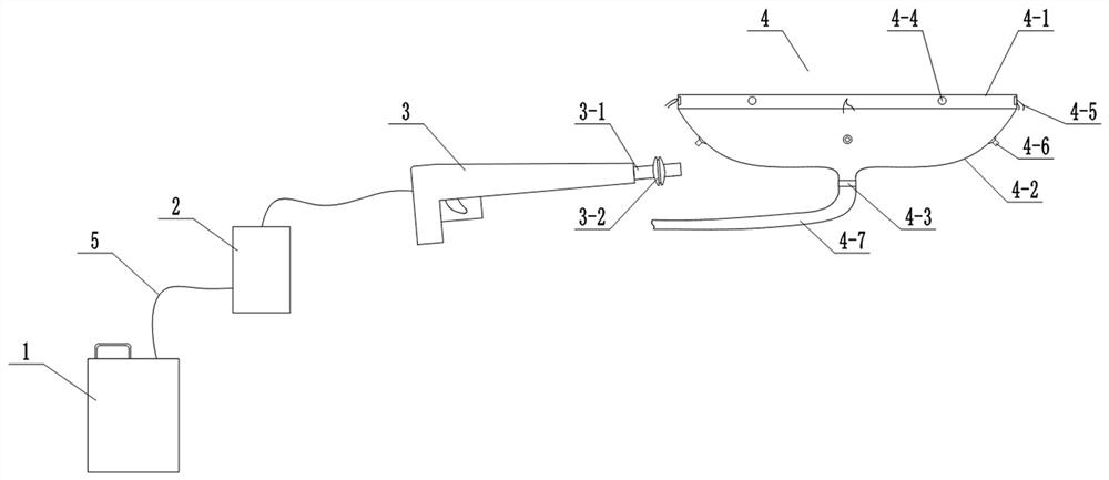
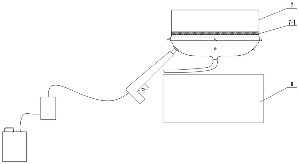
[0016] like Figure 1-Figure 2 As shown, the present invention provides a cleaning device for the heat dissipation component 7 of the wind turbine 6 , which includes a water tank 1 , a water pump 2 , a water gun 3 and a cleaning cover 4 .

[0017] The water tank 1 is connected to the water inlet of the water pump 2 through the pipeline 5, and the water outlet 4-3 of the water pump 2 is connected to the water gun 3 through the pipeline 5, and the water gun 3 includes a water spray pipe 3-1 for drainage.

[0018] The cleaning cover 4 is used to prevent the waste water from splashing during the cleaning process of the filter screen 7-1, and it includes a fixed port 4-1 for fixed connection with the bottom of the heat dissipation assembly 7, which is connected at the bottom of the fixed port 4-1. There is a conical cylinder 4-2, the bottom of the conical cylinder 4-2 is provided with a water outlet 4-3, the fixed port 4-1, and the conical cylinder 4-2 are made of good elasticity, ...


PUM


Abstract

The invention provides a wind turbine generator heat dissipation assembly cleaning device which comprises a water tank, a water pump, a water gun and a cleaning cover. The water tank is connected witha water inlet of the water pump through a pipeline, a water outlet of the water pump is connected to the water gun through a pipeline, and the water gun comprises water spraying pipes for dischargingwater; the cleaning cover comprises a fixed port used for being fixedly connected with the bottom of a heat dissipation assembly; a conical barrel is sequentially connected to the lower portion of the fixed port; a water outlet is formed in the bottom of the conical barrel; the fixed port and the conical barrel are both made of rubber which is good in elasticity, good in abrasion resistance, nonflammable and not prone to aging; the water outlet is made of engineering plastic high in hardness and good in abrasion resistance; a plurality of magnets are arranged on the inner side of the fixed port in the circumferential direction; a plurality of inserting openings corresponding to the water spraying pipes are formed in the conical barrel in the circumferential direction; and sealing plugs are arranged at the inserting openings. The wind turbine generator heat dissipation assembly cleaning device is simple and ingenious in structural design, waste water generated in the cleaning process of a filter screen in the heat dissipation assembly can be effectively prevented from splashing, and the cleaning efficiency of the heat dissipation assembly is improved.

Description

technical field [0001] The invention belongs to the technical field of cleaning equipment, and in particular relates to a cleaning device for a heat dissipation component of a wind turbine. Background technique [0002] At present, the temperature of gearboxes, generators and other components of wind turbines will be too high in summer or in strong winds. Although each fan has related heat dissipation components, dust and oil pollution often occur due to the influence of domestic land environment and climate. , catkins, etc. block the filter screen in the heat dissipation component. This phenomenon will not only reduce the cooling capacity of the heat dissipation component to the outside of the device, but also affect the air circulation at one end of the heat dissipation component due to the blockage of the filter screen, resulting in the formation of negative pressure inside the heat dissipation component, which affects the cooling fan. normal operation. [0003] Because ...

Claims


Application Information

Patent Timeline
Patent Type & Authority Applications(China)
IPC IPC(8): F03D80/55F03D80/60B08B3/02
CPCB08B3/026F03D80/55F03D80/60Y02E10/72
Inventor 赵骥郭海全路通畅吴琼
Owner 华能安徽怀宁风力发电有限责任公司
Why Eureka
Try Eureka