Micro-flow plane sealing giant magnetostrictive proportional valve

A giant magnetostrictive, flat sealing technology, applied in valve details, valve device, valve operation/release device, etc., can solve the deformation of piezoelectric ceramics, small output force, increase the thickness and quantity of piezoelectric ceramics , Increase the volume and weight of the valve, and achieve the effect of reducing the difficulty of manufacturing, wide adjustment range and high safety.

Pending Publication Date: 2021-03-16
贵州曼格维流体智能科技有限公司
View PDF1 Cites 2 Cited by
  • Summary
  • Abstract
  • Description
  • Claims
  • Application Information

AI Technical Summary

Problems solved by technology

However, the deformation of the piezoelectric ceramic itself under the action of the electric field is very small, no more than one ten-millionth of its own size, and the piezoelectric ceramic piece of the proportional valve needs to be installed in the lower casing with a mounting ring to cause deformation At this time, the material itself will expand and contract from the upper and lower directions, so that only a part of the deformation acts on the valve needle, so the movable range of the valve needle is too small; to increase its adjustment range, it is necessary to greatly increase the thickness of the piezoelectric ceramic sheet And quantity, will greatly increase the volume and weight of the valve
In addition, in order to make the deformation of the piezoelectric ceramic sheet enough to drive the valve needle and turn on the valve, and at the same time ensure that the valve needle is in the state of closing the valve when the piezoelectric ceramic sheet is not deformed, it is necessary to accurately control a certain pressure during assembly. However, the deformation and output force of the piezoelectric ceramic sheet are small, and the adaptability to pressure is poor, which makes the assembly of the proportional valve very difficult.

Method used


Image

  • Micro-flow plane sealing giant magnetostrictive proportional valve
  • Micro-flow plane sealing giant magnetostrictive proportional valve

Examples


Embodiment Construction

[0022] The technical solution of the present invention is further described below, but the scope of protection is not limited to the description.

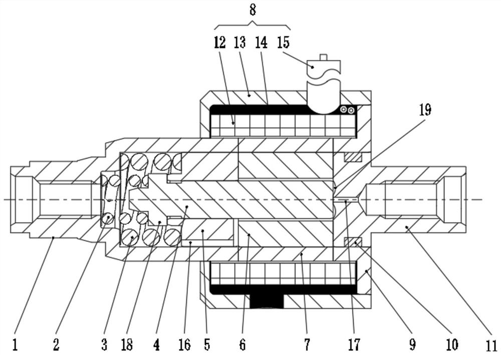
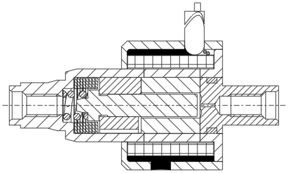
[0023] Such as figure 1 Shown is the structural representation of the present invention:

[0024] The present invention provides a micro-flow planar sealing giant magnetostrictive proportional valve, which includes a valve body 1, a valve core 4, a magnetic isolation ring 7, and a pole shoe 9. The valve body 1, magnetic isolation ring 7, and pole shoe 9 are From left to right, they are fixedly connected in turn. The magnetic isolation ring 7 is covered with a coil assembly 8, the valve body 1 is provided with a fluid inlet, the inner hole of the pole shoe 9 is provided with a valve seat 11, and the valve seat 11 is provided with a valve nozzle channel 17. , the valve core 4 is arranged on the left side of the valve seat 11, the face of the valve core 4 and the valve seat 11 facing each other is a flat sealing surface, the left end...


PUM


Abstract

The invention provides a micro-flow plane sealing giant magnetostrictive proportional valve. The micro-flow plane sealing giant magnetostrictive proportional valve comprises a valve body, a magnetismisolating ring and a pole shoe which are fixedly connected in sequence from left to right, wherein the magnetism isolating ring is sleeved with a coil assembly; a valve seat is arranged in an inner hole of the pole shoe; a valve element is arranged on the left side of the valve seat; the face, opposite to the valve seat, of the valve element is a plane sealing face; a shoulder structure is arranged at the left end of the valve element; a reset component is arranged between the shoulder structure and the wall face of the valve body; the valve element is sleeved with a supporting sleeve and a giant magnetostrictive sleeve; and the supporting sleeve and the valve element are driven to move through stretching and retracting of the giant magnetostrictive sleeve. According to the micro-flow plane sealing giant magnetostrictive proportional valve, the fluid flow can be conveniently adjusted in proportion, and the adjusting range is large; micro opening control over the valve can be achieved,and the control precision is high; the output force is large, the sealing performance is good, and the service life is long; the valve is high in response speed, good in repeatability and high in reliability; and the valve element is controlled to move through a magnetic field, and safety is high.

Description

technical field [0001] The invention relates to the technical field of valves, in particular to a micro-flow plane-sealed giant magnetostrictive proportional valve. Background technique [0002] Pressure control and flow control are important links in the attitude control power system of aerospace vehicles, especially in the field of micro-satellites and deep-space probes, such as electric propulsion systems and air-conditioning propulsion systems. During attitude control and orbit change control, the required output thrust is millinewton or micronewton level. For this requirement, the current general practice is to set a micro-flow throttle behind the solenoid valve to limit the flow through the throttle, so that the engine can only generate a constant thrust, and the thrust cannot be changed according to needs. Although the current proportional long-column flow valve and the piezoelectric ceramic proportional valve have also been developed, due to the low sensitivity of t...

Claims


Application Information

Patent Timeline
Patent Type & Authority Applications(China)
IPC IPC(8): F16K99/00F16K31/06
CPCF16K31/0655F16K31/0675F16K99/0005F16K99/0053
Inventor 苗建忠潘胜鹏龚锐
Owner 贵州曼格维流体智能科技有限公司
Why Eureka
Try Eureka