
An automatic capacitor housing cutter

A capacitor shell and automatic technology, which is applied in the direction of capacitors, capacitor manufacturing, packaging capacitor devices, etc., can solve the problem of poor service life of the automatic capacitor shell cutting machine, lack of automatic capacitor shell cutting machine, and lack of timely replenishment of goods Function and other issues, to achieve the effect of excellent cutting rate, easy collection, and avoid labor mode

Pending Publication Date: 2019-01-04
李福林
View PDF0 Cites 0 Cited by
  • Summary
  • Abstract
  • Description
  • Claims
  • Application Information

AI Technical Summary

Problems solved by technology

[0004] The purpose of the present invention is to provide an automatic capacitor casing cutting machine, to solve the problem that the currently used automatic capacitor casing cutting machine proposed in the above background technology does not have the function of replenishing goods in time, so that the interior of the automatic capacitor casing cutting machine The goods are prone to missing goods in the process of selling, and they do not have the effect of protecting the outdoor automatic capacitor shell cutting machine from the sun and rain. Yes, the outdoor automatic capacitor shell cutting machine is easily eroded by rainwater. Corrosion occurs, which makes the service life of the automatic capacitor shell cutting machine not good

Method used


Image

  • An automatic capacitor housing cutter
  • An automatic capacitor housing cutter
  • An automatic capacitor housing cutter

Examples


Embodiment Construction

[0021] The following will clearly and completely describe the technical solutions in the embodiments of the present invention with reference to the accompanying drawings in the embodiments of the present invention. Obviously, the described embodiments are only some, not all, embodiments of the present invention. Based on the embodiments of the present invention, all other embodiments obtained by persons of ordinary skill in the art without making creative efforts belong to the protection scope of the present invention.

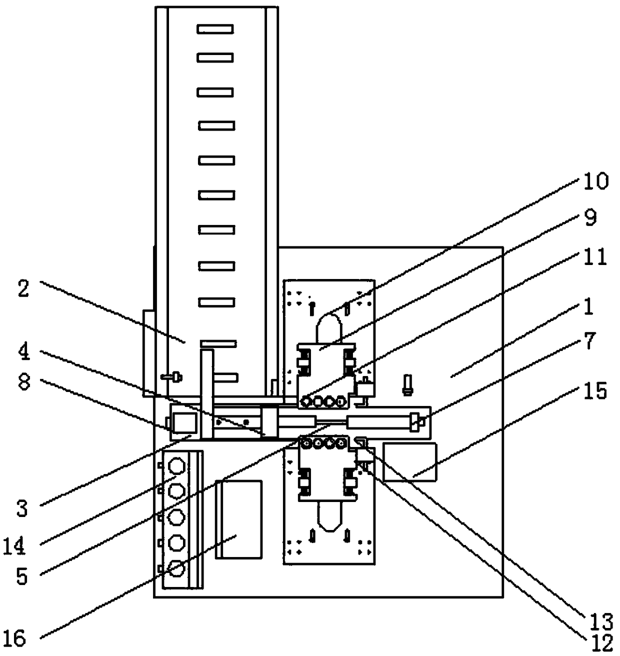
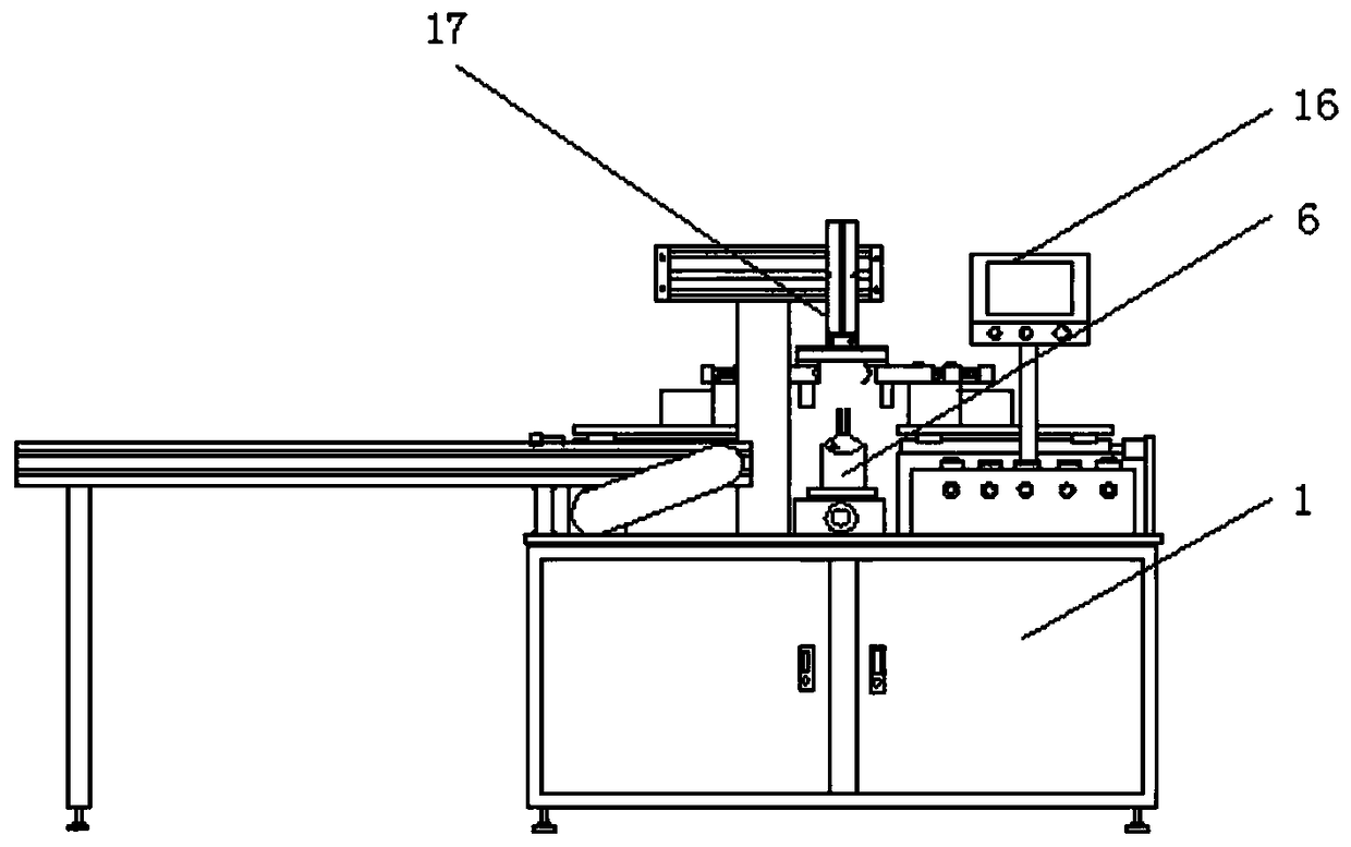
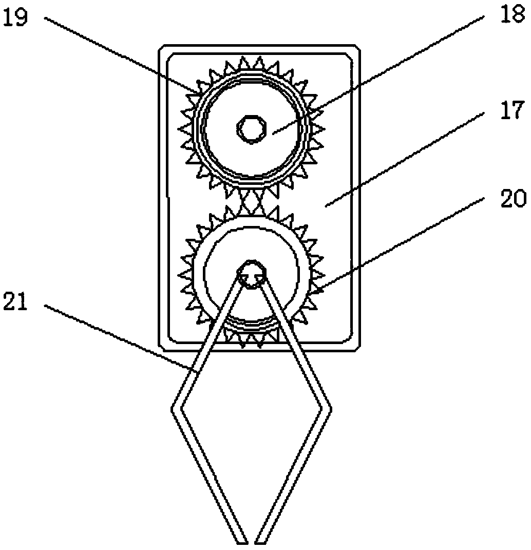
[0022] see Figure 1-5 , the present invention provides a technical solution: an automatic capacitor shell cutting machine, including a workbench 1, a conveyor belt 2, a chute 3, a clamping block 4, a threaded rod 5, a clamping head 6, and a first cylinder 7 , servo motor 8, roller shaft support 9, belt cover 10, roller shaft 11, second cylinder 12, expansion knife 13, air pressure gauge 14, exit 15, touch screen 16, movable mechanical arm 17, drive motor 18, ...


PUM


Abstract

The invention discloses an automatic capacitor shell cutting machine, including workbench, threaded rod, a first cylinder and a barometer, the left end of the worktable is provided with a conveyor belt, the upper end of the roller shaft bracket is provided with a belt cover, A second cylinder is mounted on the right side of the roller shaft bracket, The output end shaft of the second cylinder is connected with an expanding knife, the inner side of the barometer is installed with a touch screen, the rear side of the conveyor belt is installed with a movable manipulator arm, the output end shaftof the drive motor is connected with a first gear, the lower end of the first gear is installed with a second gear, and the output end shaft of the second gear is connected with a clamping arm. In the automatic capacitor shell cutting machine, under the action of external thrust, the clamping head and the clamping block can slide forward and backward in the sliding groove through the sliding block, thereby facilitating the adjustment of the spacing between the clamping head and the clamping block, facilitating the fixation of the capacitors of different specifications by the user, and facilitating the subsequent cutting of the capacitor shell.

Description

technical field [0001] The invention relates to the technical field related to capacitor processing, in particular to an automatic capacitor shell cutting machine. Background technique [0002] Capacitance, also known as "capacitance", refers to the amount of charge storage under a given potential difference. Generally speaking, charges will move under force in an electric field. When there is a medium between conductors, it will hinder the movement of charges and The charge is accumulated on the conductor, resulting in the accumulation and storage of the charge. The stored charge is called a capacitor. Because the capacitor is one of the electronic components widely used in electronic equipment, it is widely used in DC blocking, coupling, bypass, filtering, In terms of tuning circuit, energy conversion, control circuit, etc., capacitors are divided into electrolytic capacitors and solid capacitors. The shells of capacitors are all packaged with shells. In the production pro...

Claims


Application Information

Patent Timeline
Patent Type & Authority Applications(China)
IPC IPC(8): H01G13/00
CPCH01G13/003
Inventor 李福林
Owner 李福林
Learn More