Tidal-current-energy power generation device based on hydraulic transmission

A technology of power generation device and hydraulic transmission, which is applied in the fields of ocean energy power generation, hydropower generation, engine function, etc., can solve the problems of increasing the operation and maintenance cost of the unit, the number of pole pairs of the direct drive motor, and the large size of the turbine structure, etc., and achieves convenient delivery. The effect of recycling, low noise and low cost

Inactive Publication Date: 2017-06-23
DALIAN UNIV OF TECH
View PDF4 Cites 0 Cited by
  • Summary
  • Abstract
  • Description
  • Claims
  • Application Information

AI Technical Summary

Problems solved by technology

[0003] Traditional hydraulic turbine transmission forms are divided into two types: speed-up type and direct-drive type. Among them, speed-up type transmission, that is, gearbox transmission, is the most widely used method. Large, high noise, and because the gear transmission is prone to wear and other failures, the service life is relatively short, so the operation and maintenance costs of the unit are greatly increased. In addition, the water turbine is placed underwater, and maintenance will cost a lot of manpower and material resources. For the direct drive / semi-direct drive transmission, the impeller and the motor are directly coupled (without a gearbox), the low speed of the impeller leads to too many pole pairs of the direct drive motor, and the motor is bulky and heavy, which is not only expensive, but also relatively heavy heavy, difficult to hoist

Method used


Image

  • Tidal-current-energy power generation device based on hydraulic transmission
  • Tidal-current-energy power generation device based on hydraulic transmission
  • Tidal-current-energy power generation device based on hydraulic transmission

Examples


Embodiment Construction

[0019] The specific embodiments of the present invention will be described in detail below in conjunction with the technical solutions and accompanying drawings.

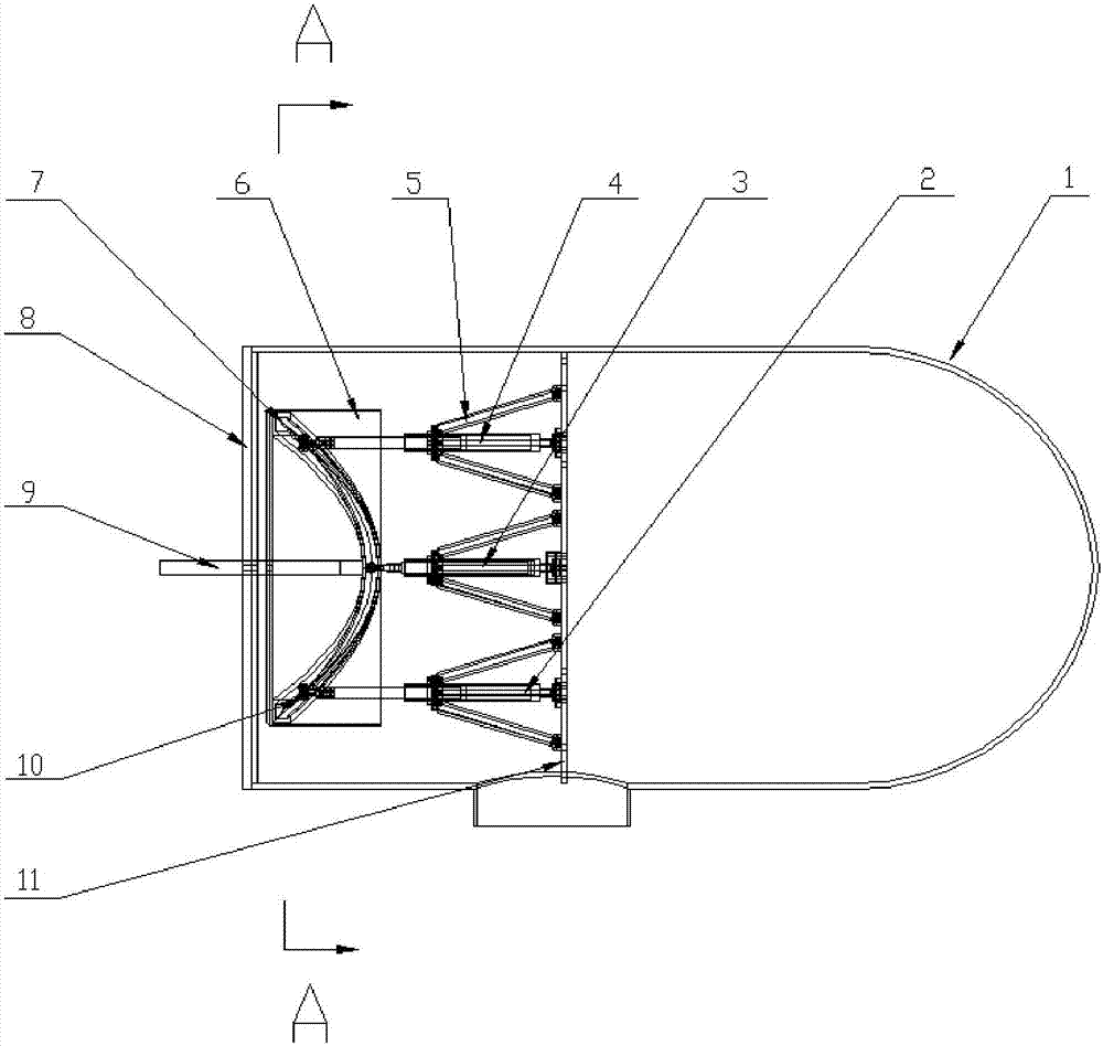
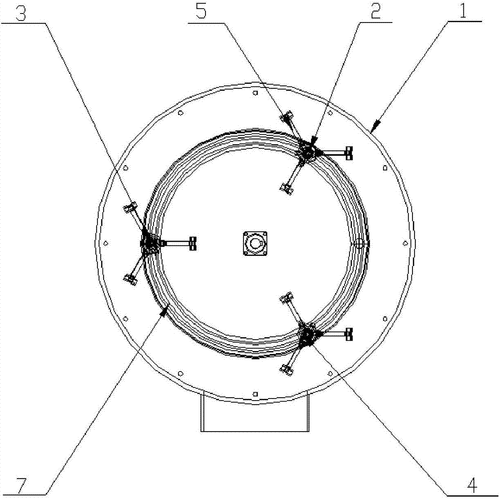
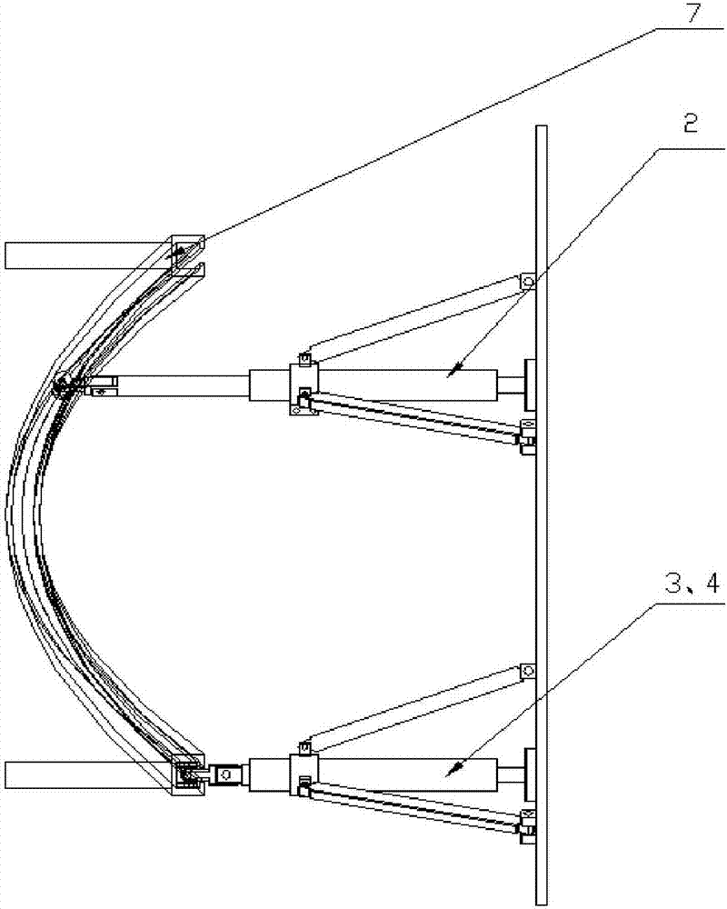
[0020] A tidal current energy power generation device based on hydraulic transmission includes a sealed cabin 1; a hydraulic cylinder A2; a hydraulic cylinder B3; a hydraulic cylinder C4; a hydraulic cylinder bracket 5; a slide rail turntable 6; Pulley 10; Fixed chassis 11 and hydraulic circuit, hydraulic circuit includes hydraulic motor, hydraulic control box, accumulator, generator, fuel tank, etc., hydraulic control box includes check valve, throttle valve, overflow valve, etc.

[0021] The tidal current energy generating device is placed in the ocean, and the sealed cabin 1 plays the role of isolating the internal structure from the external water. The whole set of equipment can be placed in the sealed cabin, and the transmission device in the sealed cabin is installed on one side of the fixed chassis 11, and the...


PUM


Abstract

The invention discloses a tidal-current-energy power generation device based on hydraulic transmission. The tidal-current-energy power generation device comprises a sealed in, a transmission shaft, a transmission device and a hydraulic loop, wherein the transmission device is arranged on one side of the sealed bin; the hydraulic loop is arranged on the other side of the sealed bin; a fixed chassis in the transmission device is fixed on the inner wall of the sealed bin; three hydraulic cylinders are uniformly arranged at intervals of 120 degrees by taking the transmission shaft as a circle center; one end of each hydraulic cylinder is fixed on the fixed chassis, and the other end of each piston rod is connected with a pulley; a sine-shaped rail is fixed on one end, close to the transmission shaft, of a sliding rail rotary disc and rotates freely along with the sliding rail rotary disc; the sliding rail rotary disc is connected with the transmission shaft and rotates along with the transmission shaft; the hydraulic loop is arranged in the sealed bin; and a complete hydraulic loop is formed through reciprocating motion of the hydraulic cylinders and the transmission shaft, and kinetic energy of tides is converted into power. The tidal-current-energy power generation device is safe and simple in structure; the sliding rail slides in a guide rail, so that efficiency is effectively improved, and the service life is prolonged; and the tidal-current-energy power generation device is free of a complex internal structure, and can be conveniently installed and recovered.

Description

technical field [0001] The invention belongs to the technical field of marine renewable energy utilization, and relates to a tidal current energy generating device based on hydraulic transmission. Background technique [0002] With the gradual depletion of traditional energy sources such as fossils, the global energy shortage and environmental pollution are becoming more and more serious. The development and utilization of clean and renewable energy will be our future research direction. Tidal current energy is a renewable energy with rich content. Energy has received great attention at home and abroad in recent years, and the significance and importance of developing and utilizing tidal current energy is self-evident. In recent years, the development and utilization of tidal current energy generation devices have made great progress worldwide. Tidal current turbines can generally be divided into vertical-axis tidal energy turbines and horizontal-axis tidal energy turbines....

Claims


Application Information

Patent Timeline
Patent Type & Authority Applications(China)
IPC IPC(8): F03B13/26F03B11/00
CPCF03B11/00F03B13/26F05B2220/706F05B2260/406Y02E10/20Y02E10/30
Inventor 陈兵刘清照苏少帅王利东
Owner DALIAN UNIV OF TECH
Why Eureka
Try Eureka