Cooking utensil

A technology of cooking utensils and air inlets, applied in the field of kitchen electrical equipment, can solve the problems of uneven heating of food, slow food heating speed, poor taste of food, etc., to achieve the effect of ensuring cooking effect, ensuring gas circulation, and ensuring uniform heating

Pending Publication Date: 2021-03-19
GUANGDONG MIDEA KITCHEN APPLIANCES MFG CO LTD +1
View PDF8 Cites 2 Cited by
  • Summary
  • Abstract
  • Description
  • Claims
  • Application Information

AI Technical Summary

Problems solved by technology

[0002] At present, cooking utensils heated by hot air are preferred by more and more users, such as figure 1 As shown, the air inlet 106' of the existing cooking utensils is generally arranged on a wall of the working cavity 104', located on the top wall or the rear wall of the worki

Method used


Image

  • Cooking utensil
  • Cooking utensil
  • Cooking utensil

Examples


Embodiment 1

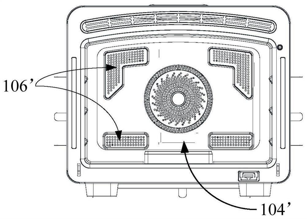
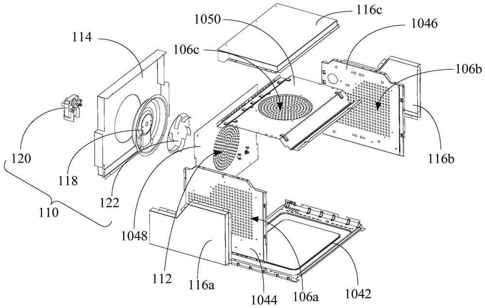
[0055] Such as image 3 and Figure 4 As shown, one embodiment of the present invention proposes a cooking utensil comprising: a body 102, the body 102 includes a working cavity 104, and the working cavity 104 is provided with at least three air inlets 106; 106 communicates with the working chamber 104 ; the driving device 110 is disposed in the air duct structure and is configured to supply air to the working chamber 104 from at least three directions through the air inlet 106 .

[0056] The cooking appliance provided by the present invention includes a body 102 , an air duct structure and a driving device 110 . Wherein, the body 102 includes a working chamber 104, the food to be cooked can be placed inside the working chamber 104; the working chamber 104 is provided with at least three air inlets 106, and the body 102 is provided with an air duct structure, and the air duct structure passes through at least three air inlets 106 and The working chamber 104 is connected, and...

Embodiment 2

[0060] Such as image 3 and Figure 4 As shown, in one embodiment of the present invention, it includes the features defined in any one of the above embodiments, and further: the cooking appliance further includes: an air return port 112, which is arranged in the working chamber 104 and communicates with the working chamber 104 and the air duct structure.

[0061] In this embodiment, an air return port 112 is provided on the working chamber 104, and the return air port 112 communicates with the working chamber 104 and the air duct structure. That is, the air duct structure communicates with the working chamber 104 through the air inlet 106 and the air return port 112 at the same time, the gas in the working chamber 104 can enter the inside of the air duct structure through the air return port 112, and the inside of the air duct structure can enter through the air inlet 106 To the working chamber 104, the circulation of the airflow is ensured.

[0062] Specifically, during th...

Embodiment 3

[0064] Such as image 3 and Figure 4 As shown, in one embodiment of the present invention, it includes the features defined in any of the above embodiments, and further: the body 102 also includes: a door body, the door body is configured to open or close the working chamber 104, the air return port 112 and the door body are located on opposite sides of the working chamber 104 .

[0065] In this embodiment, a door body is provided on the working chamber 104 for opening and closing the working chamber 104 . Wherein, when the cooking utensil needs to process food, the door body is opened to place the food in the working chamber 104; during the working process of the cooking utensil, the door body is closed to allow the airflow to flow in the closed space, reduce the loss of airflow, and improve the working efficiency of the cooking utensil. Efficiency, at the same time, keeps the food being processed free from contamination and improves operator safety. In addition, the air ...


PUM


Abstract

The invention provides a cooking utensil. The cooking utensil comprises a body, wherein the body comprises a working cavity, and the working cavity is provided with at least three air inlets; an air duct structure which is arranged on the body and communicates with the working cavity through the air inlet; and a driving device which is arranged in the air duct structure and is configured to supplyair to the working cavity from at least three directions through the air inlets. According to the cooking utensil, the air duct structure can be matched with the at least three air inlets to supply air to the working cavity, the disturbance effect of airflow in the working cavity is enhanced, the airflow can be directly blown to to-be-cooked food from three different directions, and the airflow uniformly acts on the to-be-cooked food in the working cavity; the uniform heating effect of the to-be-cooked food is ensured, and then the cooking quality of the to-be-cooked food is improved.

Description

technical field [0001] The invention relates to the field of kitchen electrical equipment, in particular to a cooking utensil. Background technique [0002] At present, cooking utensils heated by hot air are preferred by more and more users, such as figure 1 As shown, the air inlet 106' of the existing cooking utensils is generally arranged on a wall of the working cavity 104', located on the top wall or the rear wall of the working cavity 104', which makes the hot air flow can only be carried out from one direction to the food to be cooked. Heating, and the turbulence of the airflow is poor, which makes the food not evenly heated, the heating speed of the food is slow, and the taste of the cooked food is poor. Contents of the invention [0003] The present invention aims to solve at least one of the technical problems existing in the prior art. [0004] Therefore, the present invention provides a cooking utensil. [0005] The invention provides a cooking utensil, compr...

Claims


Application Information

Patent Timeline
IPC IPC(8): A47J37/06
CPCA47J37/0641
Inventor 裴杰
Owner GUANGDONG MIDEA KITCHEN APPLIANCES MFG CO LTD
Why Eureka
Try Eureka