Steel beam bolting joint structure of vertical core-penetrating plate type concrete filled steel tubular column

A technology of steel tube concrete column and joint structure, which is applied in the direction of building structure and construction, can solve the problems of affecting aesthetics, difficult construction, large amount of steel, etc., and achieve the goal of ensuring aesthetics, reasonable force, and improving bearing capacity Effect

Pending Publication Date: 2021-03-19
SHENZHEN JINXIN GREEN CONSTR LTD BY SHARE LTD
View PDF0 Cites 0 Cited by
  • Summary
  • Abstract
  • Description
  • Claims
  • Application Information

AI Technical Summary

Problems solved by technology

The concrete-filled steel tube structure is one of the important systems of prefabricated buildings. The cross-section of the traditional concrete-filled steel tube column is much larger than the width of the inner wall, causing problems such as external corners and column flutes in the room, which affect the aesthetics
The width of the narrow-section concrete-filled steel tube column is less than or equal to that of the inner wall, and it can be "hidden in the wall". affect aesthetics

Method used


Image

  • Steel beam bolting joint structure of vertical core-penetrating plate type concrete filled steel tubular column
  • Steel beam bolting joint structure of vertical core-penetrating plate type concrete filled steel tubular column
  • Steel beam bolting joint structure of vertical core-penetrating plate type concrete filled steel tubular column

Examples


Embodiment Construction

[0017] The following will clearly and completely describe the technical solutions in the embodiments of the present invention with reference to the accompanying drawings in the embodiments of the present invention. Obviously, the described embodiments are only some, not all, embodiments of the present invention.

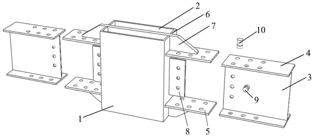
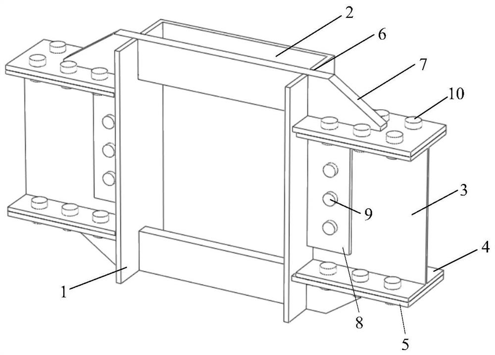
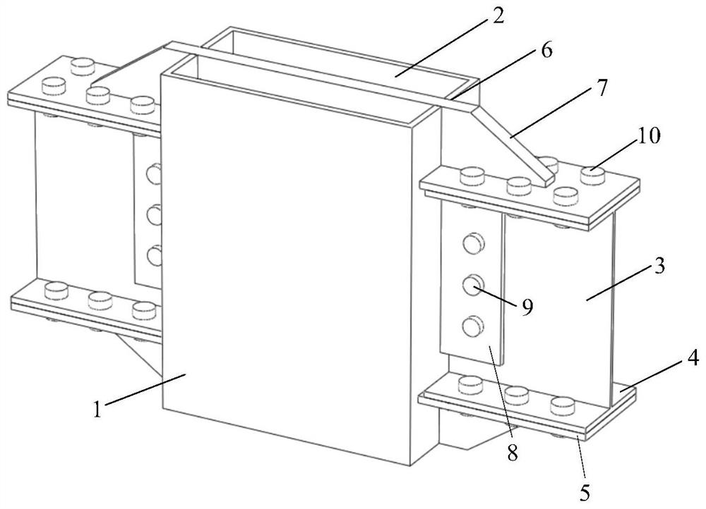
[0018] refer to Figure 1-3 , the steel beam bolted joint structure of the vertical through-core slab-type concrete-filled steel tube column, including a vertical through-core slab 7, which connects the steel-filled steel tube concrete column and the steel beam; Concrete 2 is poured, and the steel beam is located in the middle of the outer peripheral surface of the opposite short side of the outer steel pipe 1 and is connected to the outer steel pipe 1; two welds arranged horizontally in the vertical direction are arranged at the distance between the short side of the outer peripheral surface of the outer steel pipe 1 and the height of the steel beam. Cover plate 5; ...


PUM


Abstract

The invention relates to the technical field of steel-concrete structures in constructional engineering, in particular to a steel beam bolting joint structure of a vertical core-penetrating plate typeconcrete-filled steel tube column. Aiming at the problems that a beam-column joint is a key part of a fabricated building structure, the bearing capacity, anti-seismic property and the like of the structure are directly influenced by the performance of the beam-column joint, and meanwhile the construction and assembly progress is directly influenced by the structural form of the beam-column joint, the following scheme is proposed, the steel beam bolting joint structure comprises a vertical core-penetrating plate which is connected with a concrete-filled steel tubular column and a steel beam;the concrete-filled steel tubular column is formed by pouring concrete into a rectangular outer steel pipe, and the steel beam is located in the middle of the outer circumferential face of the opposite short sides of the outer steel pipe and connected with the outer steel pipe; and two welding cover plates which are horizontally arranged in the vertical direction are arranged at the distance position between the short side of the outer circumferential face of the outer steel pipe and the height of the steel beam. According to the steel beam bolting joint structure, the vertical core-penetrating plate is adopted to connect the beam column, the stress of the beam flange is transmitted to the concrete-filled steel tube column, the structure is simple, the force transmission is clear, and meanwhile, the concrete pouring is facilitated.

Description

technical field [0001] The invention relates to the technical field of steel-concrete structures in construction engineering, in particular to a steel beam bolted node structure of a vertical through-core slab-type concrete-filled steel pipe column. Background technique [0002] In recent years, the state has adopted various policies to advocate the transformation of the construction industry to the direction of green energy conservation, and an important step is to promote the development of prefabricated buildings. The concrete-filled steel tube structure is one of the important systems of prefabricated buildings. The cross-section of the traditional concrete-filled steel tube column is much larger than the width of the inner wall, which causes problems such as external corners and column flutes in the interior, which affects the aesthetics. The width of the narrow-section concrete-filled steel tube column is less than or equal to that of the inner wall, and it can be "hid...

Claims


Application Information

Patent Timeline
Patent Type & Authority Applications(China)
IPC IPC(8): E04B1/58E04B1/30
CPCE04B1/185E04B1/30
Inventor 张枫林樱舒畅王元清叶全喜王中兴
Owner SHENZHEN JINXIN GREEN CONSTR LTD BY SHARE LTD
Why Eureka
Try Eureka