Paraffin removal device for oil field and using method thereof

A wax removal and oilfield technology, applied in cleaning equipment, earthwork drilling, wellbore/well parts, etc., can solve the problem that the wax removal device cannot be applied to oil wells, etc., and achieve the effect of high wax removal efficiency

Active Publication Date: 2021-03-19
山东奥士德石油技术有限公司
View PDF5 Cites 1 Cited by
  • Summary
  • Abstract
  • Description
  • Claims
  • Application Information

AI Technical Summary

Problems solved by technology

[0003] The current wax removal device generally adopts the method of mechanical wax removal, but due to the different inner diameters of oil wells, the wax removal device cannot be applied to all oil wells with different inner diameters

Method used


Image

  • Paraffin removal device for oil field and using method thereof
  • Paraffin removal device for oil field and using method thereof
  • Paraffin removal device for oil field and using method thereof

Examples


Embodiment 1

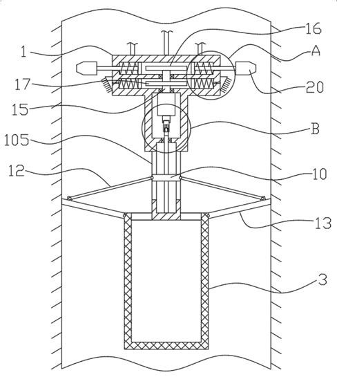
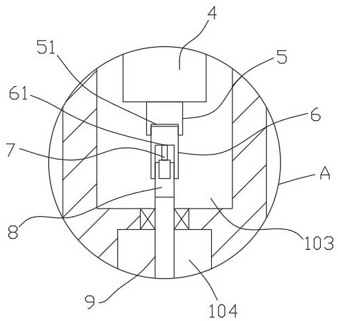
[0027] refer to Figure 1-5 , a wax removal device for oilfields, comprising a device body 1 integrally formed by three cylinders whose diameters successively decrease from top to bottom, and a first rotating chamber 101, a second rotating chamber 101, and a The rotating cavity 102, the third rotating cavity 103 and the fourth rotating cavity 104, the outer wall of the lower end of the device body 1 is uniformly fixedly connected with a plurality of connecting rods 2 in the circumferential direction, and the ends of the plurality of connecting rods 2 away from the device body 1 are jointly fixedly connected with leaks. The cylinder 3 and the inner top wall of the third rotating cavity 103 are fixedly installed with a biaxial motor 4, and the upper and lower output ends of the biaxial motor 4 are respectively fixedly connected with an upper drive shaft 15 and a lower drive shaft 5, and the upper end of the upper drive shaft 15 runs through The second rotating chamber 102 extend...

Embodiment 2

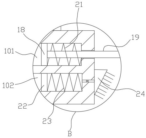
[0031] It is basically the same as Embodiment 1, except that the softening mechanism includes a second cam 17 fixedly sleeved on the upper drive shaft 15, and a plurality of second sliding plates 22 are uniformly slidably connected in the circumferential direction of the second rotating chamber 102. The side of the second slide plate 22 far away from the second cam 17 and the inner wall of the second rotating chamber 102 are fixedly connected with a sealed elastic bag 23, the elastic bag 23 is an air bag with elastic recovery ability, and utilizes the extrusion of the second cam 17 and its own recovery ability, can suck or extract hot water, the second rotating chamber 102 is embedded with a one-way water outlet pipe communicating with the elastic bag 23, the other end of the one-way water outlet pipe is connected with a nozzle 24, and the elastic bag 23 passes through the one-way water outlet pipe. The water pipe is connected with a hot water tank, and the above-mentioned one-...


PUM


Abstract

The invention discloses a paraffin removal device for an oil field and a using method of the paraffin removal device, and relates to the technical field of oil field paraffin removal, the paraffin removal device comprises a device body integrally formed by three cylinders with the diameters sequentially decreased from top to bottom, and a first rotating cavity, a second rotating cavity, a third rotating cavity and a fourth rotating cavity are sequentially formed in the device body from top to bottom. A plurality of connecting rods are evenly and fixedly connected to the outer wall of the lowerend of the device body in the circumferential direction, the ends, away from the device body, of the multiple connecting rods are jointly and fixedly connected with a leaking cylinder, and a double-shaft motor is fixedly installed on the inner top wall of the third rotating cavity. The device has the advantages that by arranging the knocking mechanism, the softening mechanism, the clutch mechanism and the opening and closing mechanism, the knocking hammer, the rigid scraping plate and the elastic scraping plate can adapt to oil wells with different inner diameters, knocking of the knocking hammer, spraying of hot water, scraping of wax attached to the well wall and collection of the wax in the leakage barrel are sequentially conducted, wax removal is effectively achieved, and the wax removal efficiency is high.

Description

technical field [0001] The invention relates to the technical field of wax removal in oil fields, in particular to a wax removal device for oil fields and a use method thereof. Background technique [0002] Crude oil contains different amounts of paraffin, which is generally in a dissolved state under the conditions of the reservoir. When the crude oil rises from the bottom of the well and flows through the oil pipe, the temperature and pressure gradually decrease, and the wax gradually precipitates, accumulates, and accumulates on the pipe wall, which is called oil well waxing. It makes the inner diameter of the oil pipe smaller, affects the production capacity of the well, and in severe cases, the oil well stops production. For oil wells in different oil fields and reservoirs, due to differences in crude oil properties and wax content, temperature and pressure, flow conditions and tubing surface conditions, the positions where wax deposition begins are also different. Sp...

Claims


Application Information

Patent Timeline
Patent Type & Authority Applications(China)
IPC IPC(8): E21B37/00E21B37/02
CPCE21B37/00E21B37/02
Inventor 高超王志崔伟托君丽朱定
Owner 山东奥士德石油技术有限公司
Why Eureka
Try Eureka