
Electromagnetic heating and ball collecting device for oil pipeline and heating and ball collecting method of electromagnetic heating and ball collecting device

An oil pipeline and oil outlet pipeline technology, which is applied in the field of electromagnetic heating ball collecting devices for oil pipelines, can solve the problems of inability to meet the development needs of intelligent oil fields, waste of crude oil and wax remover, damage to enameled wire insulation, etc., and is beneficial to environmental protection. , The effect of improving the ball collection efficiency and saving energy

Active Publication Date: 2022-06-24
西安川秦石油科技有限公司
View PDF11 Cites 0 Cited by
  • Summary
  • Abstract
  • Description
  • Claims
  • Application Information

AI Technical Summary

Problems solved by technology

[0002] At present, there are more than 1,000 wax removal and ball collection mechanisms for oil pipelines in Changqing Oilfield. They use ordinary copper enameled wires with a voltage of 380V and a power frequency of 50Hz for direct heating. The heating time is as long as 2 hours, and the heating efficiency is low. It is necessary to open the outer iron shell and dig out the quartz sand filled around it, so it is difficult to overhaul
Long-term oil leakage will also damage the insulation of the enameled wire, cause a short circuit accident, burn out the heating equipment, and cause the heating to stop
At this time, the oil production workers had to use iron wire to fish out the balls stained with a large amount of wax, and rinse them with wax remover repeatedly. The labor intensity was high, and a large amount of crude oil and wax remover were wasted.
Especially when collecting balls in winter, due to the low temperature in the ball collecting mechanism, the crude oil becomes lumpy, and the wax removal ball is covered with a large amount of wax. It needs to be heated to melt the oil and wax to facilitate the removal of the ball. Meet the development needs of intelligent oilfields

Method used


Image

  • Electromagnetic heating and ball collecting device for oil pipeline and heating and ball collecting method of electromagnetic heating and ball collecting device
  • Electromagnetic heating and ball collecting device for oil pipeline and heating and ball collecting method of electromagnetic heating and ball collecting device
  • Electromagnetic heating and ball collecting device for oil pipeline and heating and ball collecting method of electromagnetic heating and ball collecting device

Examples


Embodiment 1

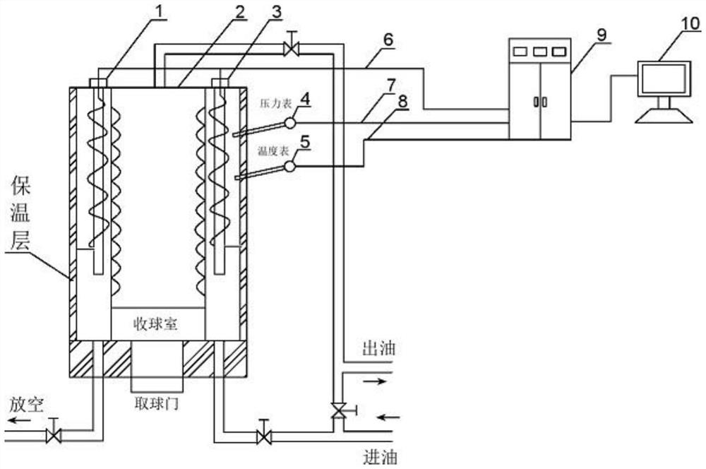
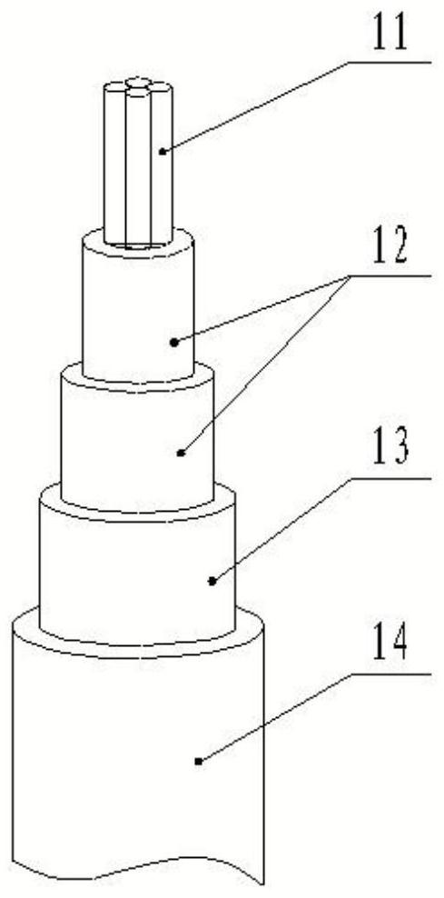
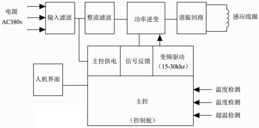
[0040] refer to Figure 1-Figure 3 The shown electromagnetic heating ball collecting device for oil pipeline includes a ball collecting mechanism 2, an electromagnetic heating control mechanism 9, an electromagnetic heating mechanism, an intelligent monitoring mechanism and a remote controller 10; It is connected with the oil inlet pipeline and the oil outlet pipeline. The bottom end of the ball collection mechanism 2 is connected with the oil inlet pipeline through the pipeline. The bottom end of the ball collection mechanism 2 is also provided with a venting pipeline. There are pipeline control switches in the space, between the oil outlet pipeline and the oil inlet pipeline, between the oil inlet pipeline and the bottom end of the ball collecting mechanism 2 and on the emptying pipeline, and the pipeline control switch is connected with the electromagnetic heating control mechanism 9 by electrical signals; The electromagnetic heating mechanism is fixedly connected in the ba...

Embodiment 2

[0044] refer to figure 1 The shown electromagnetic heating ball collecting device for oil pipeline, on the basis of the first embodiment, the ball collecting mechanism 2 at least includes an inner hollow cylinder cast by high pressure steel; The separator, each separator is evenly provided with through holes, and the diameter of the through holes is smaller than the diameter of the wax balls received; an electromagnetic heating mechanism is arranged between each separator and the inner side wall of the cylinder; the center of the bottom surface of the cylinder is provided with an electromagnetic heating mechanism. A ball-taking port is provided, and a ball-taking gate is arranged on the ball-taking port.

[0045] In a specific application, the ball collecting mechanism 2 is essentially a barrel-shaped structure cast by high pressure steel. The arrangement of the partition can effectively prevent the wax ball from passing through, and effectively avoid the wax ball hitting the...

Embodiment 3

[0049] refer to figure 1 In the shown electromagnetic heating ball collecting device for oil pipeline, on the basis of the second embodiment, the inner and outer side walls and the lower end surface of the cylinder are provided with thermal insulation layers.

[0050] In specific applications, the setting of the thermal insulation layer makes the heating effect better and saves energy.


PUM


Abstract

The invention belongs to the technical field of oil field oil pipeline paraffin removal and ball collection, and relates to an oil pipeline electromagnetic heating and ball collection device and a heating and ball collection method thereof. The electromagnetic heating ball collecting device comprises a ball collecting mechanism, an electromagnetic heating control mechanism, an electromagnetic heating mechanism, an intelligent monitoring mechanism and a remote controller. Pipeline control switches are arranged between the top end of the ball collecting mechanism and an oil outlet pipeline, between the oil outlet pipeline and an oil inlet pipeline, between the oil inlet pipeline and the bottom end of the ball collecting mechanism and on an emptying pipeline. The electromagnetic heating control mechanism controls the temperature and pressure of the electromagnetic heating mechanism and the intelligent monitoring mechanism in real time in the heating process; the pipeline control switch is controlled by the electromagnetic heating control mechanism, so that paraffin removal, heating and ball taking processes of balls in an oil pipeline of an oil field are controlled, the ball collecting efficiency is improved by 1.5 times, and the heating time is shortened by half. The device is safe in use process, long in service life, unattended and simple to use and maintain.

Description

technical field [0001] The invention belongs to the technical field of removing wax and collecting balls for oil pipelines in oil fields, and in particular relates to an electromagnetic heating ball collecting device for oil pipelines and a method for heating and collecting balls. Background technique [0002] At present, there are more than 1,000 wax removal and ball collection mechanisms for oil pipelines in Changqing Oilfield. They are directly heated by ordinary copper enameled wires with 380V voltage and 50Hz power frequency. The heating time is as long as 2 hours, and the heating efficiency is low. At the same time, the ball collection mechanism often leaks oil. When it is necessary to open the outer iron shell and dig out the quartz sand filled around it, maintenance is difficult. Long-term oil leakage will also damage the insulation of the enameled wire, cause a short circuit accident, burn out the heating equipment, and stop heating. At this time, oil workers had t...

Claims


Application Information

Patent Timeline
Patent Type & Authority Applications(China)
IPC IPC(8): H05B6/02H05B6/06F16L55/46
CPCH05B6/02H05B6/06F16L55/46F16L2101/12Y02P10/25
Inventor 高宝元李昭辉郑维师张磊谭欢韩婧婧
Owner 西安川秦石油科技有限公司
Learn More