Two-stage variable valve lift mechanism for internal combustion engine

A valve lift, internal combustion engine technology, applied in the direction of machines/engines, mechanical equipment, engine components, etc., can solve problems such as energy waste, inability to accurately and effectively complete cam state switching, and low thermal efficiency

Active Publication Date: 2021-03-19
JAPHL POWERTRAIN SYST
View PDF6 Cites 1 Cited by
  • Summary
  • Abstract
  • Description
  • Claims
  • Application Information

AI Technical Summary

Problems solved by technology

In traditional internal combustion engines, the valve lift is fixed, which leads to the same valve lift opening regardless of the heavy load or light load conditions, resulting in energy waste and lo

Method used


Image

  • Two-stage variable valve lift mechanism for internal combustion engine
  • Two-stage variable valve lift mechanism for internal combustion engine
  • Two-stage variable valve lift mechanism for internal combustion engine

Examples


Embodiment Construction

[0031] Below with reference to the accompanying drawings, through the description of the embodiments, the specific embodiments of the present invention, such as the shape, structure, mutual position and connection relationship between the various parts, the role and working principle of the various parts, etc., will be further described. Detailed instructions:

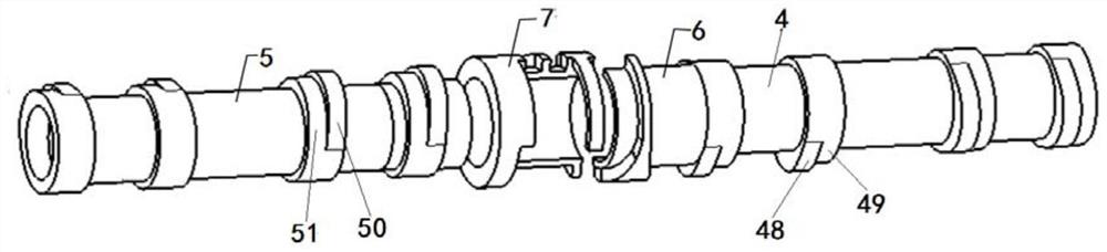
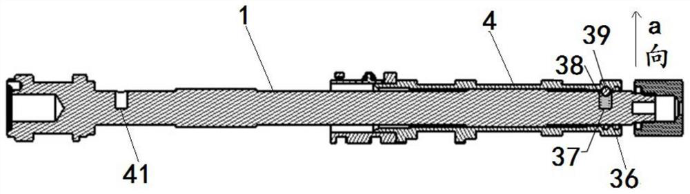
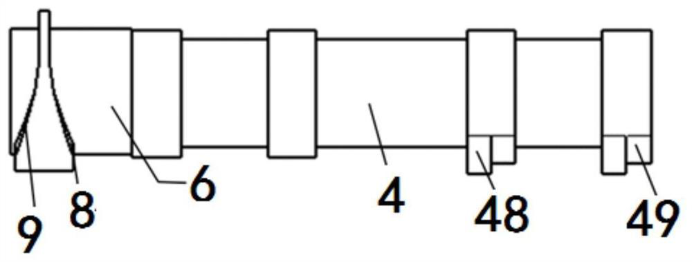
[0032] as attached figure 1 - attached Figure 11 As shown, the present invention is a two-stage variable valve lift mechanism for an internal combustion engine, comprising a mandrel 1, a valve pin A2, a valve pin B3, a movable sleeve sleeve A4 and a shaft sleeve B5 on the mandrel 1, and a shaft sleeve The adjustment part A6 is set on the A4, the adjustment part B7 is set on the bushing B5, the displacement slope a8 and the displacement slope b9 are set on the adjustment part A6, the displacement slope c10, the displacement slope d11, the displacement slope e12, and the displacement slope f13 are set on the adjustment...


PUM


Abstract

The invention provides a two-stage variable valve lift mechanism for an internal combustion engine, and is applied to the technical field of automobile engines (internal combustion engines). An adjusting part B(7) of the two-stage variable valve lift mechanism for the internal combustion engine is machined and formed by using an MIM process; an adjusting part A(6) is machined and formed; a valve pin B(3) is arranged in a structure which can act on the adjusting part B(7) to drive a shaft sleeve B(5) to axially move leftwards relative to a spindle (1); and the valve pin B(3) is also arranged ina structure which can act on the adjusting part A(6) to drive a shaft sleeve A(4) to axially move rightwards relative to the spindle (1). According to the two-stage variable valve lift mechanism forthe internal combustion engine, the cam state switching of an engine can be accurately realized, the engine can more scientifically complete combustion and work in the optimal working state under different working condition requirements, and the heat efficiency is improved.

Description

technical field [0001] The invention belongs to the technical field of automobile engines (internal combustion engines), and more specifically relates to a two-stage variable valve lift mechanism for internal combustion engines. Background technique [0002] As the power machinery with the highest thermal efficiency and the most widely used at present, the internal combustion engine generates 90% of the total power of power plants used in the world, and is the main consumption channel of petroleum energy in the world. On the one hand, as the number of cars increases, the oil consumption of internal combustion engines will increase rapidly, and the contradiction between oil supply and demand will inevitably become increasingly serious. While consuming a large amount of energy, internal combustion engines are also the biggest source of pollution to the atmospheric environment, especially in cities. Innovating internal combustion engine technology is of great significance for s...

Claims


Application Information

Patent Timeline
IPC IPC(8): F01L13/00
CPCF01L13/0036F01L2013/0078
Inventor 王雷范礼丁万龙李海萌刘玉坪邵璠甄子源
Owner JAPHL POWERTRAIN SYST
Why Eureka
Try Eureka