gasoline engine impeller

A gasoline engine and impeller technology, applied in mechanical equipment, engine components, machines/engines, etc., can solve the problems of inability to meet the air volume required for machine cooling, poor power performance of the whole machine, low cooling air flow, etc., and improve the cooling effect of oil. , The effect of stable power and stable impeller strength

Active Publication Date: 2021-09-28
重庆华世丹动力科技有限公司
View PDF0 Cites 0 Cited by
  • Summary
  • Abstract
  • Description
  • Claims
  • Application Information

AI Technical Summary

Problems solved by technology

However, the cooling air flow rate of the existing gasoline engine is relatively low, resulting in high engine oil temperature during high-load operation, resulting in poor power performance and short service life of the whole machine.
This type of impeller currently on the market cannot meet the air volume required for machine cooling

Method used


Image

  • gasoline engine impeller
  • gasoline engine impeller
  • gasoline engine impeller

Examples


Embodiment 1

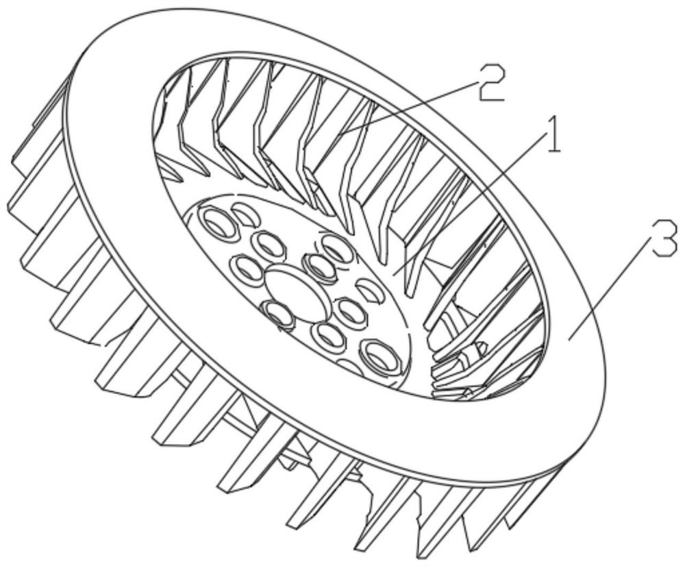
[0029] Example 1, such as Figure 1~5 As shown, the gasoline engine impeller of the present invention includes an impeller mounting base 1 and a plurality of blades 2 distributed on the edge of the end surface of the impeller mounting base 1 with the impeller mounting base 1 as the center, and a flow channel is formed between two adjacent blades 2, and the The end surface of the blade 2 away from the impeller mounting base 1 is fixed with a wind pressure ring 3, the center of the wind pressure ring 3 forms an air inlet, the wind pressure ring 3 is arranged in parallel with the impeller mounting base 1, and the wind pressure ring 3 is arranged in parallel with the impeller mounting base 1. The ring 3 is conical and its inner side is connected to the blade 2. The outer ring of the air pressure ring 3 extends outwards and has not passed the outside of the blade 2. The angle of the center of the section of the air pressure ring 3 is 130°~ 150°.

[0030] In the device of the prese...

Embodiment 2

[0031] Embodiment 2, the difference between this embodiment and Embodiment 1 is that the inner surface of the blade 2 is formed with an S-shaped inner arc segment, which is beneficial to the blade 2 to disturb the air at the air inlet when the impeller is running at high speed , so that the air at the air inlet forms a greater negative pressure swirl, thereby improving the air intake efficiency. In the present invention, the blade 2 is hook-shaped at the lower side of the air pressure ring 3, and the blade 2 extends to the inner side of the air pressure ring 3 to form a straight line, which can improve the air outlet efficiency.

[0032] Specifically, in this embodiment, the inner arc segment includes a first arc segment 4, a second arc segment 5 and a third arc segment 6, and the arc direction of the second arc segment 5 is the same as that of the first arc segment. The arc directions of the circular arc segment 4 and the third circular arc segment 6 are opposite, and the fir...

Embodiment 3

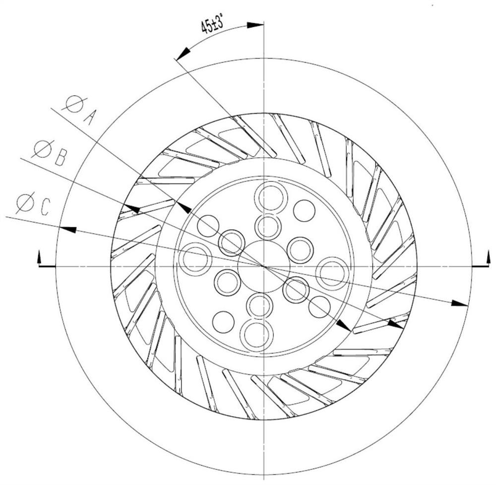
[0033] Embodiment 3. The difference between this embodiment and Embodiment 2 is that in this embodiment, the relative inclination angle between the blade 2 and the radial direction of the circumference is 45±3°, and the inclination angle of the blade 2 directly affects the negative pressure of the air intake. The design angle is 45±3°, which is the best angle through CAE analysis and test verification. Compared with ordinary impellers, the air intake can be increased by 5%.

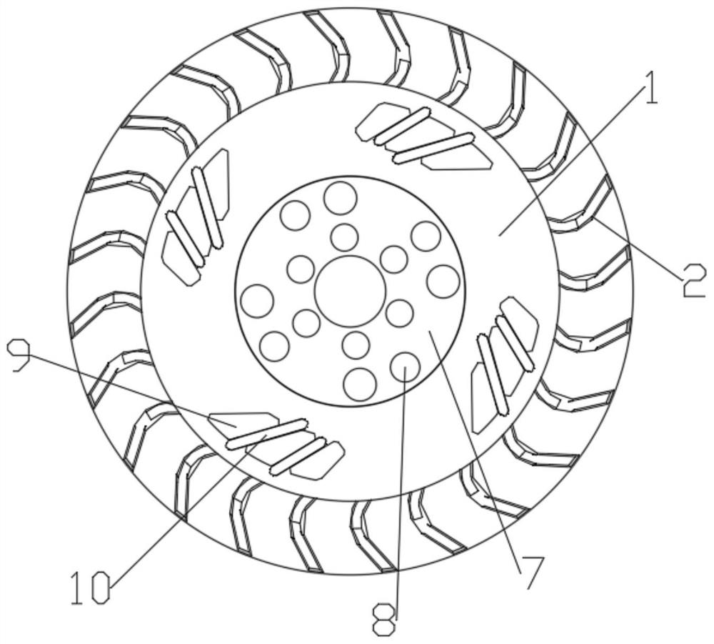
[0034] In this embodiment, the center of the impeller mounting seat 1 is provided with an impeller seat 7, and several installation holes 8 are opened on the impeller seat 7.

[0035] In this embodiment, several groups of heat dissipation holes 9 are opened on the impeller mounting base 1, and through holes 10 are formed between two adjacent heat dissipation holes 9, and the blades 2 located at the through holes 10 extend out of the through holes. After 10, it extends outward, which can be used for heat d...


PUM


Abstract

The invention discloses a gasoline engine impeller, belonging to the technical field of impellers, comprising an impeller mounting seat and a plurality of blades distributed on the edge of the end surface of the impeller mounting seat centered on the impeller mounting seat, and a flow channel is formed between two adjacent blades. A wind pressure ring is fixed on the end surface of the blade away from the end of the impeller mounting seat. The center of the air pressure ring forms an air inlet. The air pressure ring is arranged in parallel with the impeller mounting seat. The air pressure ring is conical and The inner side thereof is connected with the blades, the outer ring of the air-compressing ring extends outwards and submerges the outer side of the blades, and the center angle of the section of the air-compressing ring is 130°-150°. The device of the invention reduces the air intake and outflow resistance by optimizing the structure, so that the total air volume of the gasoline engine is increased compared with the general impeller at the same speed, the oil cooling effect is significantly improved, the power is higher, and the power is continuously stable.

Description

technical field [0001] The invention belongs to the technical field of impellers, in particular to a gasoline engine impeller. Background technique [0002] In the prior art, when a gasoline engine is running, fuel combustion and engine running friction will generate a large amount of heat. However, the cooling air flow rate of the existing gasoline engine is relatively low, which leads to excessive engine oil temperature during high-load operation, resulting in poor power performance and short service life of the complete machine. This type of impeller currently on the market cannot meet the air volume required for machine cooling. Contents of the invention [0003] In view of this, the purpose of the present invention is to provide a gasoline engine impeller. By optimizing the structure, the air intake and outflow resistance are reduced, so that the total air volume of the gasoline engine is increased compared with the general impeller at the same speed, and the oil coo...

Claims


Application Information

Patent Timeline
Patent Type & Authority Patents(China)
IPC IPC(8): F01M5/00F01P5/02F04D29/28F04D29/30
CPCF01M5/002F01P5/02F04D29/282F04D29/30
Inventor 杨佺何飞唐勇周波戴真强
Owner 重庆华世丹动力科技有限公司
Why Eureka
Try Eureka