Gaze point estimation method and system, processor and device

A gaze point and normalization technology, applied in the field of information processing, can solve problems such as large distance, inability to meet miniaturization and light weight, and large volume

Pending Publication Date: 2021-03-19
BEIJING 7INVENSUN TECH
View PDF0 Cites 0 Cited by
  • Summary
  • Abstract
  • Description
  • Claims
  • Application Information

AI Technical Summary

Problems solved by technology

The distance between the two light sources needs to be set relatively large, which makes the eye-tracking device produced by the existing eye-tracking method relatively large in size, and cannot meet the miniaturization and light-weight goals required by users.

Method used


Image

  • Gaze point estimation method and system, processor and device
  • Gaze point estimation method and system, processor and device
  • Gaze point estimation method and system, processor and device

Examples


Embodiment 1

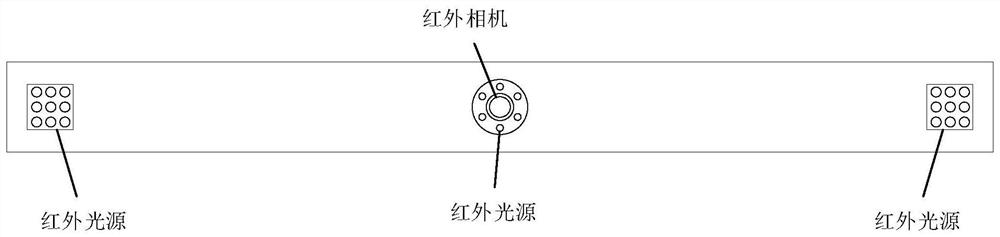
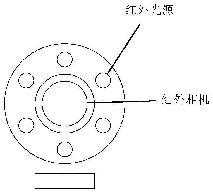
[0079] see figure 2 , which shows a schematic structural diagram of a module of an eye-tracking device provided by an embodiment of the present application. In this module, only one infrared light source and one infrared camera are required, wherein the infrared light source is used as a bright pupil light source , what needs to be explained is that for a bright pupil to appear, the light source needs to be located near the optical axis of the camera or on the same straight line as the optical axis of the camera. In this way, due to the mirror reflection principle of the pupil, the image formed by the pupil on the image is not black, but very bright illustration. Using the light source and camera module in the eye-tracking device can greatly reduce the size of the module, and achieve the purpose of miniaturization and light weight of the eye-tracking device. figure 2 The infrared light source in represents the single light source in the embodiment of this application, that ...

Embodiment 2

[0096] In the second embodiment of the present application, a method for calculating the pupil spot center data of both eyes is provided, see Figure 5 , the method includes:

[0097] S201. Collect human eye feature information of the original image;

[0098] S202. Acquire pupil image features and light spot image features of both eyes according to the human eye feature information;

[0099] S203. Calculate and obtain the pupil image coordinates according to the pupil image features;

[0100] S204. Calculate and obtain the coordinates of the spot image according to the feature of the spot image.

[0101] In this embodiment, the pupil spot center data of the two eyes includes pupil image coordinates and spot image coordinates.

[0102] After the human eye feature information is obtained in the original image, the spot image can be obtained by searching in the original image according to the feature of the spot image as a search condition. For example, the search can be perf...

Embodiment 3

[0111] Since there are many light sources in the existing eye-tracking device, the control logic for the brightness in order to realize effective gaze point estimation is relatively complicated. Embodiment 3 of the present application provides an exposure gain control logic, which only needs to realize the control according to the gray value of the pupil.

[0112] see Figure 6 , which shows a schematic flowchart of an exposure gain adjustment method, the method comprising:

[0113] S301. Calculate the average gray value of the pupil area according to the original image;

[0114] S302. Determine whether to adjust the set exposure gain according to the average gray value, so that the acquired original image satisfies the spot search condition.

[0115] According to the image characteristics of the pupil area, the pupil area is found in the original image, and then the image corresponding to the pupil area is converted into a grayscale image, so that the gray value of each pix...


PUM


Abstract

The invention discloses a gaze point estimation method and system, and the method is used for a sight tracking device with a single camera and a single coaxial light source, and comprises the steps: obtaining an original image captured from the single camera; collecting human eye feature information of the original image, and calculating pupil light spot center data of two eyes based on the humaneye feature information; based on the pupil light spot center data, acquiring an initial PCR vector by calculation, wherein the PCR vector represents a vector that the light spot center points to thepupil center; normalizing the initial PCR vector by using a preset distance factor to obtain a target PCR vector; and calculating to obtain gaze point information according to the target PCR vector. Only pupil light spot center data is applied during gaze point estimation, the problem that gaze point estimation can be achieved only through two sets of light sources is solved, and therefore the number of light sources of an existing sight tracking device can be reduced, and miniaturization and light weight of the sight tracking device are achieved.

Description

technical field [0001] The present invention relates to the technical field of information processing, in particular to a gaze point estimation method, system, processor and equipment. Background technique [0002] With the development of human-computer interaction technology, eye tracking technology has been widely used. Eye tracking, also known as gaze tracking, is the technique of measuring eye movement to estimate the line of sight and / or gaze of the eyes. [0003] Existing gaze tracking technologies are generally based on multi-light source single camera or multi-light source multi-camera settings. The light source is generally divided into two types: one is that the light source is separated from the camera to form a normal pupil face image (also called dark pupil), and this light source is called dark pupil light source; the other is the iris with the light source and the camera coaxial Reflected light causes the camera's pupils to glow (also known as bright pupils)...

Claims


Application Information

Patent Timeline
Patent Type & Authority Applications(China)
IPC IPC(8): G06K9/00
CPCG06V40/193
Inventor 王云飞
Owner BEIJING 7INVENSUN TECH
Why Eureka
Try Eureka