Stroke sling chain type shot blasting cleaning machine

A technology of shot blasting cleaning machine and shot blasting machine, which is applied in the direction of abrasive jetting machine tools, used abrasive processing devices, abrasive materials, etc., can solve the problems of time-consuming and laborious, poor shot blasting effect of equipment, etc., and achieve improved shot blasting speed, Reduce the labor load and improve the effect of shot blasting

Inactive Publication Date: 2021-03-23
诸城市大宇铸造机械有限公司
View PDF0 Cites 2 Cited by
  • Summary
  • Abstract
  • Description
  • Claims
  • Application Information

AI Technical Summary

Problems solved by technology

Due to the relatively simple structure of the existing shot blasting machine, when performing shot blasting treatment on larger workpieces, the staff needs to turn it over, which is time-consuming and laborious, and the shot blasting effect of the equipment is poor, so a stroke is required Hanging chain shot blasting machine

Method used


Image

  • Stroke sling chain type shot blasting cleaning machine
  • Stroke sling chain type shot blasting cleaning machine
  • Stroke sling chain type shot blasting cleaning machine

Examples


Embodiment Construction

[0015] The specific implementation manners of the present invention will be further described in detail below in conjunction with the accompanying drawings and embodiments. The following examples are used to illustrate the present invention, but are not intended to limit the scope of the present invention.

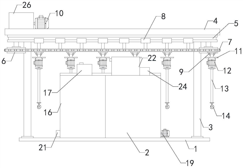
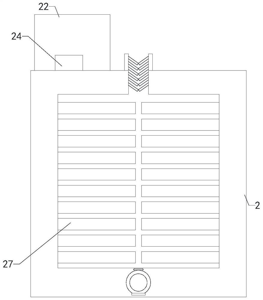
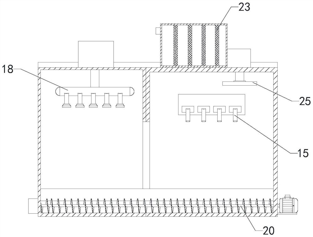
[0016] Such as Figure 1 to Figure 3 As shown, the stroke hanging chain type shot blasting machine of the present invention includes a base 1, a shot blasting machine 2, multiple sets of supports 3, a top plate 4, slide rails 5, multiple sets of transmission shafts 6, chains 7, and multiple sets of chute 8 , multiple sets of suspension rings 9, first motor 10, multiple sets of second motors 12, multiple sets of connecting rods 13 and multiple sets of hooks 14, the bottom end of the shot blasting machine 2 is connected with the top of the base 1, and the shot blasting machine 2 The top of the shot blasting machine 2 is provided with a first reserved groove, the right end o...


PUM


Abstract

The invention relates to the technical field of shot blasting cleaning machines, in particular to a stroke sling chain type shot blasting cleaning machine. A plurality of groups of second motors are started, a plurality of groups of lifting hooks are made to drive a plurality of groups of materials to rotate, then a first motor is started, a chain is made to operate through transmission of a plurality of groups of transmission shafts, and the rotating materials are conveyed into a shot blasting machine through a feed port of the shot blasting machine. The materials are subjected to shot blasting through a plurality of groups of shot blasting nozzles in the shot blasting machine, and then the shot-blasted materials are discharged through a discharge port of the shot blasting machine, so that the labor amount of workers is reduced, the shot blasting speed of the equipment is increased, and the shot blasting effect of the equipment is improved. The stroke sling chain type shot blasting machine comprises a base, the shot blasting machine, a plurality of groups of supports, a top plate, a sliding rail, the plurality of groups of transmission shafts, the chain, a plurality of groups of sliding grooves, a plurality of groups of lifting rings, the first motor, the plurality of groups of second motors, a plurality of groups of connecting rods and the plurality of groups of lifting hooks. The bottom end of the shot blasting machine is connected with the top end of the base, a first reserved groove is formed in the top end of the shot blasting machine, and the feed port is formed in the right end of the shot blasting machine.

Description

technical field [0001] The invention relates to the technical field of shot blasting machines, in particular to a stroke hanging chain type shot blasting machine. Background technique [0002] Shot blasting machine, also known as shot blasting machine, refers to casting equipment that uses high-speed projectiles thrown by a shot blaster to clean or strengthen the surface of castings. The shot blasting machine can shake out sand, remove core and clean the casting at the same time. In some areas, it is also called sandblasting machine and sand blasting machine verbally. Due to the relatively simple structure of the existing shot blasting machine, when performing shot blasting treatment on larger workpieces, the staff needs to turn it over, which is time-consuming and laborious, and the shot blasting effect of the equipment is poor, so a stroke is required Hanging chain shot blasting machine. Contents of the invention [0003] In order to solve the above-mentioned technica...

Claims


Application Information

Patent Timeline
Patent Type & Authority Applications(China)
IPC IPC(8): B24C3/00B24C9/00
CPCB24C3/00B24C9/00B24C9/003
Inventor 赵仁伟
Owner 诸城市大宇铸造机械有限公司
Why Eureka
Try Eureka