BMS new energy battery positioning and capping device

A new energy and battery technology, applied in the direction of battery assembly, secondary battery manufacturing, transportation and packaging, etc., can solve the problems of high labor intensity, manual capping and low positioning efficiency, so as to reduce labor intensity, reduce practicability, Improve the effect of investment

Active Publication Date: 2021-03-23
南京金邦动力科技有限公司
View PDF7 Cites 3 Cited by
  • Summary
  • Abstract
  • Description
  • Claims
  • Application Information

AI Technical Summary

Problems solved by technology

[0005] Aiming at the deficiencies of the prior art, the present invention provides a positioning capping device for BMS new energy batteries, which solves the problems of low manual capping and positioning efficiency and high labor intensity

Method used


Image

  • BMS new energy battery positioning and capping device
  • BMS new energy battery positioning and capping device
  • BMS new energy battery positioning and capping device

Examples


Embodiment 1

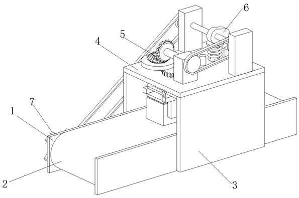
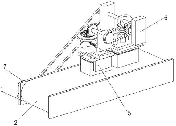
[0034] A positioning and capping device for BMS new energy batteries, such as Figure 1-Figure 6 As shown, the fixed plate 1 is included, and the number of the fixed plates 1 is set to two, and two rollers 2 are rotatably connected between the two fixed plates 1, and the surfaces of the two rollers 2 are connected by a transmission belt, and the two fixed plates 1 The surface of the support plate 3 is welded with a support plate 3, the top of the support plate 3 is welded with a mounting plate 4, the top of the mounting plate 4 is respectively provided with a positioning mechanism 5 and a capping mechanism 6, and the positioning mechanism 5 is located at the front of the capping mechanism 6, and the fixed plate 1 The left side is provided with transmission mechanism 7.

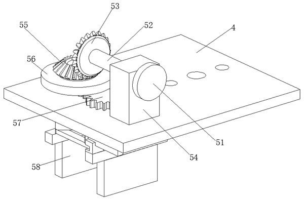
[0035] In this embodiment, the positioning mechanism 5 includes a No. 1 pulley 51, a connecting shaft 52 is welded at the axis of the No. 1 pulley 51, a No. 1 bevel gear 53 is welded to the left end of the con...

Embodiment 2

[0041] Such as Figure 6-Figure 8 As shown, the surface of the No. 2 pulley 61 is connected to the surface of the No. 1 pulley 51 through a belt, the surface of the No. 1 cam 63 is in contact with the upper surface of the push plate 67, and the surface of the transmission shaft 62 is connected in rotation with the inner wall of the support block 64. , the surface of the guide post 68 is slidingly connected with the inner wall of the mounting plate 4, and the two ends of the back-moving spring 66 are in contact with the lower surface of the push plate 67 and the upper surface of the mounting plate 4 respectively. The reason why this device is selected for belt transmission is that the belt has Good elasticity, can ease the impact and vibration during work, the movement is smooth and noiseless, and the belt slips on the wheel when the load is too large, so it can prevent other parts from being damaged and play a role of safety protection. The belt is an intermediate part, and it ...


PUM


Abstract

The invention relates to the technical field of BMS, and discloses a BMS new energy battery positioning and capping device. The BMS new energy battery positioning and capping device comprises two fixing plates, two rollers are rotatably connected between the two fixing plates, the surfaces of the two rollers are in transmission connection through a conveying belt, and supporting plates are weldedto the surfaces of the two fixing plates; and a mounting plate is welded to the tops of the supporting plates, a positioning mechanism and a capping mechanism are arranged at the top of the mounting plate correspondingly, and a transmission mechanism is arranged on the left side of each fixing plate. A battery box can be automatically positioned and straightened through the positioning mechanism,so that operation is convenient when the battery box is conveyed to the next procedure to be capped; and the situation that the battery box is not straight, consequently, a top cover cannot be completely closed, and then the rework rate is increased and the cost investment is increased is prevented, the battery box obtained after positioning can be automatically capped through the capping mechanism, manual capping of workers is not needed, and the working efficiency is improved.

Description

technical field [0001] The invention relates to the technical field of BMS, in particular to a positioning capping device for a BMS new energy battery. Background technique [0002] BMS building equipment management system is a system that implements comprehensive management of building equipment monitoring systems and public safety systems. [0003] After the BMS new energy battery is installed in the battery box, the top needs to be capped. In the past, most of the battery boxes were manually capped, which would increase the labor intensity of the workers and lower the work efficiency. The existing capping equipment requires workers to seal the battery. The box is placed neatly by hand, and then transported to the bottom of the capping device through the conveyor belt for capping, which is less practical. Therefore, a positioning and capping device for BMS new energy batteries is proposed to solve the above-mentioned problems. Contents of the invention [0004] (1) Solv...

Claims


Application Information

Patent Timeline
Patent Type & Authority Applications(China)
IPC IPC(8): B65G47/24H01M10/04
CPCB65G47/24H01M10/0404Y02P70/50Y02E60/10
Inventor 田伟
Owner 南京金邦动力科技有限公司
Why Eureka
Try Eureka