Drying device for chemical fertilizer

A drying device and fertilizer technology, applied in the directions of drying, drying machine, heating device, etc., can solve the problems of poor drying effect, difficult drying of chemical fertilizers, low efficiency, etc., so as to improve drying effect, improve efficiency, The effect of improving uniformity

Inactive Publication Date: 2021-03-23
孟杨唯伊
View PDF0 Cites 0 Cited by
  • Summary
  • Abstract
  • Description
  • Claims
  • Application Information

AI Technical Summary

Problems solved by technology

[0003] In the production process of chemical fertilizers, in order to facilitate later storage and sales, it is usually necessary to use a drying device to dry chemical fertilizers. Because chemical fertilizers are usually easy to form small lumps due to moisture, it is easy to cause small lumps during drying. The inside of the fertilizer is difficult to dry, the drying effect is poor, and the efficiency is low

Method used


Image

  • Drying device for chemical fertilizer
  • Drying device for chemical fertilizer
  • Drying device for chemical fertilizer

Examples


Embodiment 1

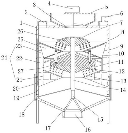
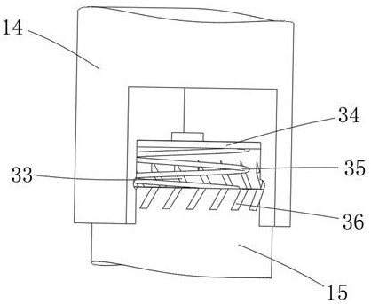
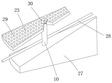
[0025] refer to Figure 1-4 , a drying device for chemical fertilizers, comprising a cylinder 1, the top of the cylinder 1 is provided with a feeding mechanism, and the top outer wall of the cylinder 1 is fixedly connected with an exhaust shell 2 communicating with the cylinder 1, the exhaust shell 2 The top outer wall is fixedly connected with the exhaust pipe 6, the bottom outer wall of the cylinder body 1 is provided with a discharge port 16, and a fixed rod 15 is provided directly above the discharge port 16, and the bottom outer wall of the fixed rod 15 is connected to the cylinder through a support rod 17. The side inner wall of the body 1, the top of the fixed rod 15 is provided with a core rod 14, and the bottom end of the core rod 14 is provided with a cylindrical groove, the fixed rod 15 is slidably connected to the side inner wall of the cylindrical groove, and the side inner wall of the cylindrical groove is provided with a threaded groove 33, the top of the side o...

Embodiment 2

[0035] refer to Figure 5 , a drying device for chemical fertilizers. Compared with Embodiment 1, the top outer wall of the material distribution plate 7 is fixedly connected with a collecting ring 31, and the bottom of the side outer wall of the collecting ring 31 is provided with evenly distributed feeding troughs. Mouth 32.

[0036] When the present invention is in use: compared with Embodiment 1, when the blanking falls on the material distribution plate 7, it will first fall into the collection ring 31, and then fall from the blanking notch 32 on the side of the collection ring 31, thereby preventing fertilizer Unable to fall to the middle position of the material distribution plate 7 and cause the material falling from the surroundings of the material distribution plate 7 to be uneven, so that the material blanking is more uniform.


PUM


Abstract

The invention belongs to the technical field of chemical fertilizer production, particularly relates to a drying device for chemical fertilizer, and provides the following scheme for solving the problems in the prior art. The drying device comprises a barrel, a feeding mechanism is arranged at the top of the barrel, an exhaust shell communicated with the barrel is fixedly connected to the outer wall of the top of the barrel, and an exhaust pipe is fixedly connected to the outer wall of the top of the exhaust shell; and a discharging opening is formed in the outer wall of the bottom of the barrel, and a fixing rod is arranged over the discharging opening. Falling chemical fertilizer is scattered through bent rods, so that the chemical fertilizer is more dispersed, the drying effect of the chemical fertilizer is improved, the chemical fertilizer passing through the upper surface of a middle block can be dispersed, the drying effect of the chemical fertilizer is further improved, poor influence caused by damp air passing through the upper surface of an upper material guide area is prevented, and the drying efficiency is further improved; and the situation that the chemical fertilizercannot fall to the center of a material distributing plate, and consequently the material distributing plate disperses the chemical fertilizer unevenly is prevented, and the chemical fertilizer dispersion uniformity is improved.

Description

technical field [0001] The invention relates to the technical field of chemical fertilizer production, in particular to a drying device for chemical fertilizer. Background technique [0002] Chemical fertilizers are fertilizers made by chemical methods that contain one or several nutrient elements needed for the growth of crops. The abbreviation of chemical fertilizers is called unit fertilizers that contain only one nutrient element that can indicate the content, such as nitrogen fertilizer, phosphorus fertilizer, Potassium fertilizers and minor macroelement fertilizers and trace element fertilizers, chemical fertilizers containing two or three of the three nutrients nitrogen, phosphorus, and potassium, and their contents can be indicated, are called compound fertilizers or mixed fertilizers. [0003] In the production process of chemical fertilizers, in order to facilitate later storage and sales, it is usually necessary to use a drying device to dry chemical fertilizers. ...

Claims


Application Information

Patent Timeline
IPC IPC(8): F26B11/14F26B23/04F26B25/00F26B25/04F26B25/12
CPCF26B11/14F26B23/04F26B25/002F26B25/04F26B25/12
Inventor 孟杨维伊
Owner 孟杨唯伊
Why Eureka
Try Eureka