Vibration abnormality diagnosis method and system for intelligent main shaft

A technology of abnormal diagnosis and spindle, which is applied in the testing of mechanical components, testing of machine/structural components, measuring devices, etc., can solve problems such as inconvenient implementation, and achieve the effect of simple structure and easy implementation

Active Publication Date: 2021-03-23
深圳市玄羽科技有限公司
View PDF8 Cites 0 Cited by
  • Summary
  • Abstract
  • Description
  • Claims
  • Application Information

AI Technical Summary

Problems solved by technology

But this reflective optical intensity modulation optical fiber vibration measurement technology is not easy to implement, and can only achieve vibration measurement in one direction

Method used


Image

  • Vibration abnormality diagnosis method and system for intelligent main shaft
  • Vibration abnormality diagnosis method and system for intelligent main shaft
  • Vibration abnormality diagnosis method and system for intelligent main shaft

Examples


Embodiment 1

[0049] The present invention provides a vibration abnormality diagnosis system of an intelligent spindle. The main improvement of the system lies in the vibration data collection of the spindle in the radial plane. Therefore, the following content mainly focuses on the vibration data collection part of the system.

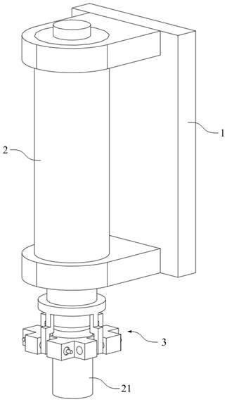
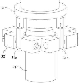
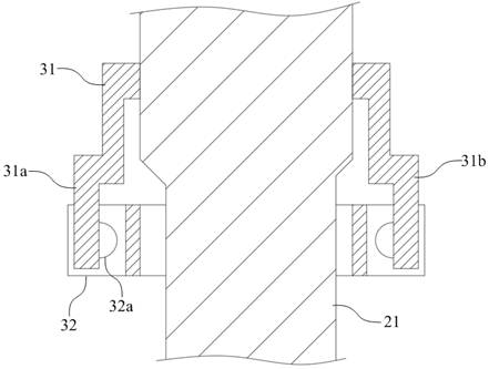
[0050] refer to Figure 1-4 , in the embodiment of the present invention, the system includes a vibration monitoring device 3 , the vibration monitoring device 3 is set on the output shaft 21 of the main shaft unit 2 , and the main shaft unit 2 is set on the frame 1 .

[0051] The vibration monitoring device 3 includes a vibration pickup ring 31 and a fixed ring 32 , both of which are sleeved on the output shaft 21 of the spindle unit 2 . Wherein, the vibration pickup ring 31 can vibrate with the vibration of the output shaft 21 ; and the fixed ring 32 is fixed on the frame 1 through a fixing member (not shown in the figure), so as to be fixed relative to the outpu...

Embodiment 2

[0074] refer to Figure 6-7 , On the basis of the above-mentioned embodiment 1, a plurality of elastic arms 33 are arranged between the vibration pickup ring 31 and the fixed ring 32, specifically, the elastic arms 33 are made of . The vibration pickup ring 31 is elastically connected to the fixing ring 32 through the elastic arm 33 . The elastic arm 33 can weaken the torsion force exerted by the output shaft 21 on the pickup ring 31 , further preventing the pickup ring 31 from rotating due to the rotation of the output shaft 21 .


PUM


Abstract

The invention discloses a vibration abnormality diagnosis method and system for an intelligent main shaft, and the method comprises the steps: sleeving a vibration pickup ring and a fixed ring on a main shaft, respectively arranging cantilevers at the front, rear, left and right sides of the vibration pickup ring, arranging a light path corresponding to the cantilevers on the fixed ring, and respectively arranging a laser and a photoelectric detector at an incident port and an emergent port of the light path; and arranging a fracture into which the cantilever is inserted in the optical path. The vibration pickup ring can pick up vibration of the main shaft in the horizontal direction and the vertical direction in the radial plane, the vibration pickup ring can drive the cantilevers to movein the fracture along with vibration of the main shaft, transmission of light in a light path is interfered, and the intensity of light received by the photoelectric detector is changed. In this way,the light intensity received by the photoelectric detector can be collected, the light intensity change is calculated, a mapping relation between the light intensity change and the vibration displacement is obtained through calibration and least square method fitting, and then the vibration condition of the main shaft in the radial plane is obtained according to the mapping relation. And the vibration abnormity of the main shaft is diagnosed according to the obtained vibration condition.

Description

technical field [0001] The invention relates to the technical field of spindle vibration detection and diagnosis, in particular to a method and system for abnormal vibration diagnosis of an intelligent spindle. Background technique [0002] With the rapid development of industrial big data technology, machine tools are also developing in the direction of flexibility, integration and intelligence. As the core functional part of the machine tool, the performance of the spindle determines the technical level of the machine tool, and the intelligence of the spindle has become an inevitable research and development trend. [0003] Existing studies believe that the intelligent spindle has at least the following characteristics: 1) Perception, that is, the spindle can perceive the running state of breeding, actively detect and communicate with the CNC system and operators, and share this information; 2) Decision-making, that is, the spindle can autonomously Process the perceived m...

Claims


Application Information

Patent Timeline
IPC IPC(8): G01M13/028
CPCG01M13/028
Inventor 李鸿峰贾昌武谭国豪张宸
Owner 深圳市玄羽科技有限公司
Why Eureka
Try Eureka