
Method for additive manufacturing repair of ultra-thin structures

An additive manufacturing and ultra-thin technology, which is applied in the field of additive manufacturing and repair of ultra-thin structures, can solve problems such as difficulty in meeting design requirements for dimensional accuracy, deformation of ultra-thin structures, and long time required to expand the use range of equipment and quickly Effects of repairing and reducing equipment cost

Active Publication Date: 2021-05-18
AECC SHANGHAI COMML AIRCRAFT ENGINE MFG CO LTD +1
View PDF9 Cites 0 Cited by
  • Summary
  • Abstract
  • Description
  • Claims
  • Application Information

AI Technical Summary

Problems solved by technology

The first solution requires a special repair head, which requires high equipment, and conventional equipment is difficult to meet the requirements, and if a small spot is used throughout the repair process, the repair rate is low
The second option, profiling tooling takes a long time to process, and because the tooling and the sample are partially metallurgically combined, it is easy to cause tool vibration during the machining removal process after repairing, which will cause errors in machining and even lead to the direct occurrence of ultra-thin structures. Deformation, resulting in the dimensional accuracy after repair is difficult to meet the design requirements

Method used


Image

  • Method for additive manufacturing repair of ultra-thin structures
  • Method for additive manufacturing repair of ultra-thin structures
  • Method for additive manufacturing repair of ultra-thin structures

Examples


no. 1 example

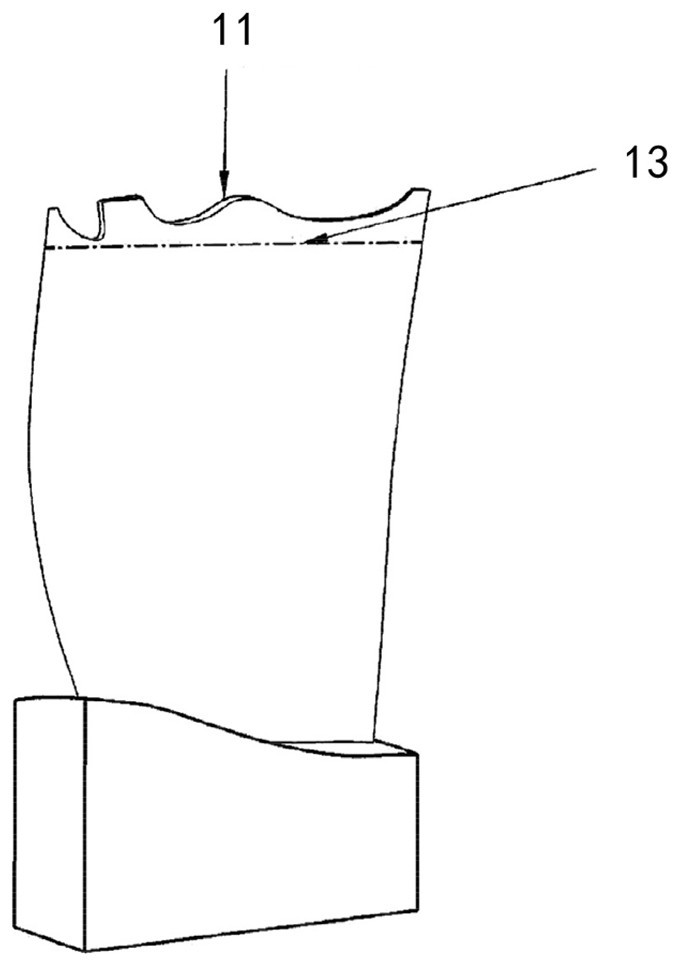
[0064] The first embodiment: compressor blade tip repair

[0065] (1) Blade tip damage machining: The entire blade tip (including the damaged area) is machined and removed.

[0066] (2) Three-dimensional modeling of the area to be repaired: 3D modeling of the area to be repaired is carried out by modeling software such as UG and CAD.

[0067] (3) Model processing: Add margin (0.5mm) to the 3D model of the area to be repaired, layered slicing, and path planning.

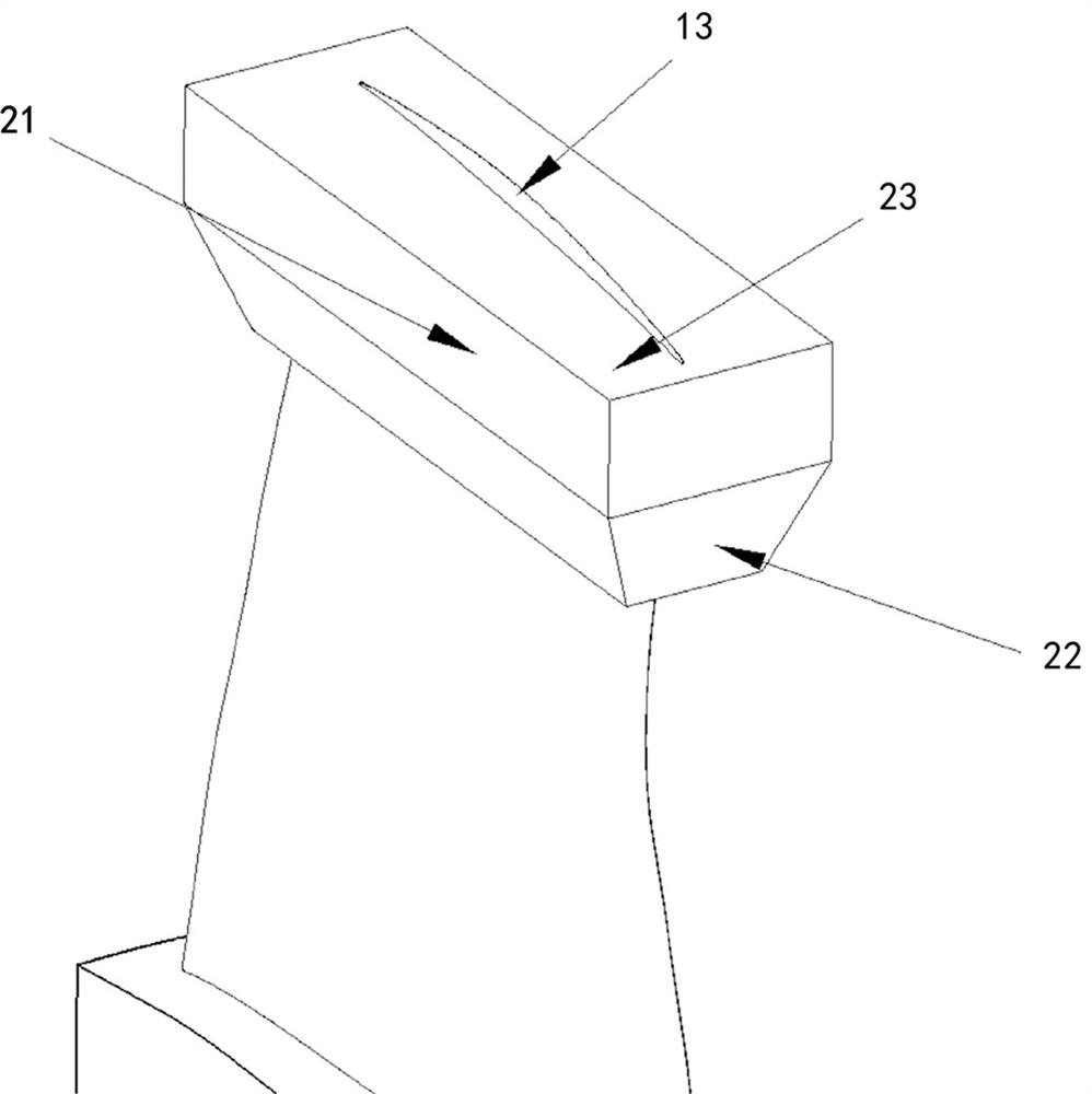
[0068] (4) Adaptive clamping at the bottom of the area to be repaired: Adaptively build powder loading devices 21 on both sides of the bottom of the area to be repaired with soft metal materials such as aluminum foil, and fix them to the compressor blades with high-temperature resistant adhesive tape 22, such as figure 2 shown.

[0069] (5) Filling the powder loading device with powder: Fill the powder loading device 21 with Ti17 metal powder 23, and scrape off the powder so that the powder is flush with the bottom...

no. 2 example

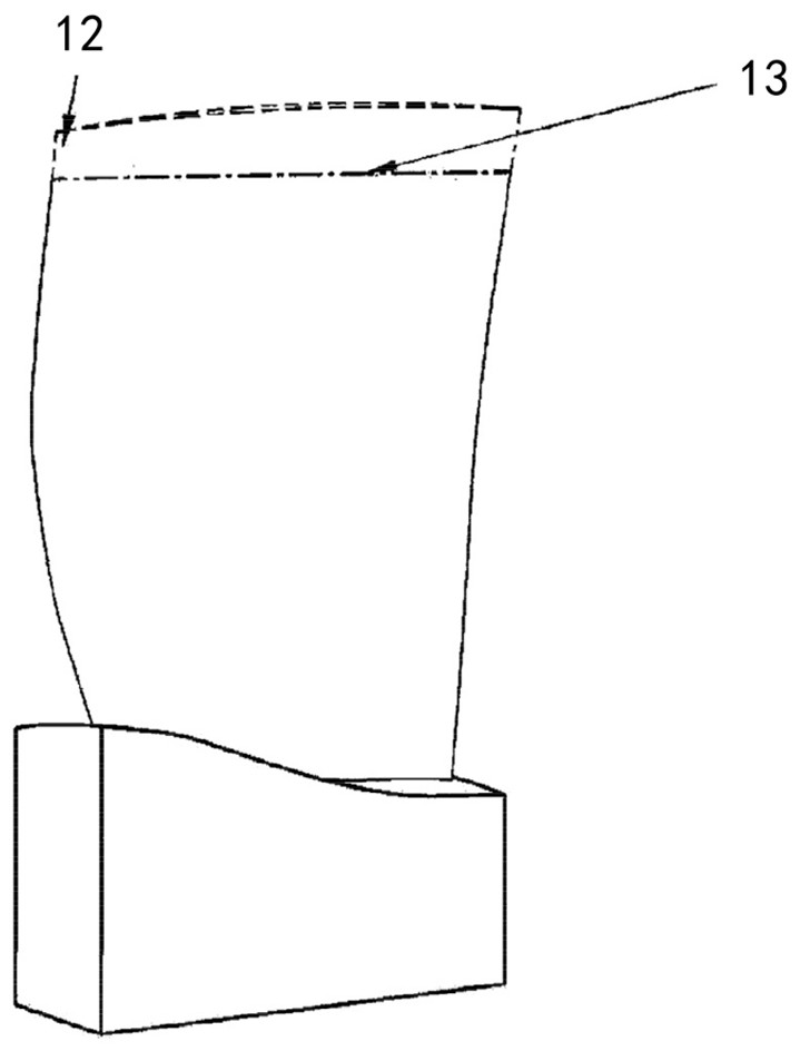
[0074] The second embodiment: repairing the front and rear edges of compressor blades

[0075] (1) Machining of front and rear edge damage: The damage area of ​​front and rear edges is machined and removed according to the principle of minimum damage to form a regular trapezoidal groove.

[0076] (2) Three-dimensional modeling of the area to be repaired: 3D modeling of the area to be repaired is carried out by modeling software such as UG and CAD.

[0077] (3) Model processing: The 3D model of the area to be repaired is subjected to margin addition processing (0.5-1mm), layered slice processing, and path planning processing.

[0078] (4) Adaptive clamping at the bottom of the area to be repaired: Adaptively build powder loading devices 21 on both sides of the bottom of the area to be repaired with soft metal materials such as aluminum foil, and fix them to the compressor blades with high-temperature resistant adhesive tape 22, such as image 3 shown.

[0079] (5) Fill the po...


PUM

PropertyMeasurementUnit
thicknessaaaaaaaaaa

Abstract

The invention relates to a method for superthin structure additive manufacturing and repairing. The method comprises the following steps: machining and removing the damaged area of ​​the ultra-thin structure; obtaining a three-dimensional model of the area to be repaired in the ultra-thin structure; processing the three-dimensional model of the area to be repaired; constructing a powder-carrying device around the bottom of the area to be repaired, Fill the powder in the powder loading device to be flush or tangent to the bottom surface of the area to be repaired; use high-energy beams or auxiliary heating devices to melt, sinter or solidify the powder in the powder loading device around the outer contour of the ultra-thin structure, and combine with The outer contours of the ultra-thin structure are combined to form a thickened outer contour structure, which becomes an adaptive tooling; according to the planned path obtained from model processing, the area to be repaired is repaired by additive manufacturing technology. The invention can achieve the following beneficial technical effects: ultra-thin structures can be repaired without ultra-small spot high-energy beam equipment or thickening tooling.

Description

technical field [0001] The invention relates to the technical field of additive manufacturing, in particular to a method for repairing ultra-thin structures through additive manufacturing. Background technique [0002] Ultra-thin structures are widely used in the field of aeroengine blades. In recent years, with the further development of manufacturing technology, the integration of engine blisks and blades has become a mainstream development trend. Different from conventional split blisks, if the overall blisk is damaged, the damaged part cannot be replaced, and the entire blisk needs to be replaced, which will greatly increase the cost of the engine. It is of great significance to reduce the cost of the engine to use related repair technologies to repair the blisks damaged during processing or service, so as to restore their performance and avoid the scrapping of the blisks. Traditional repair methods such as arc welding have a series of problems such as high heat input, ...

Claims


Application Information

Patent Timeline
Patent Type & Authority Patents(China)
IPC IPC(8): B22F7/08B22F10/28B22F10/64B22F10/66B22F12/50B33Y10/00B33Y30/00B33Y40/20
CPCB22F7/062B22F3/24B33Y10/00B33Y30/00B33Y40/00B22F2007/068B22F2003/248B22F2003/247Y02P10/25B22F10/25B22F10/28B23P6/007B22F5/04B22F10/64B22F10/66B22F10/36B23K26/342F01D5/005B33Y40/20B33Y80/00B33Y50/02B22F7/08B23K26/032B23K26/70B23K26/60B23K2101/001B23K2103/08C22C14/00C22F1/183B22F2999/00B22F10/85B22F2998/10
Inventor 焦宗戈付俊付鑫雷力明闫雪
Owner AECC SHANGHAI COMML AIRCRAFT ENGINE MFG CO LTD
Learn More