Force-limiting damping device
A shock-absorbing device and force-limiting technology, which is applied to striking tools, hand-held tools, manufacturing tools, etc., can solve the problems that users are not easy to hold, recoil, and feel uncomfortable for users, so as to reduce the number of knocks and reduce the number of hits. The time required, the reduction of energy loss and noise, the effect of convenient maintenance and replacement
- Summary
- Abstract
- Description
- Claims
- Application Information
AI Technical Summary
Problems solved by technology
Method used
Image

Examples
Embodiment Construction
[0047] In order to understand the technical features and practical effects of the present invention in detail and realize them according to the contents of the description, the preferred embodiment shown in the accompanying drawings will be described in detail as follows:
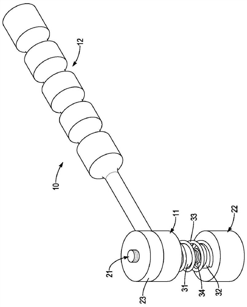
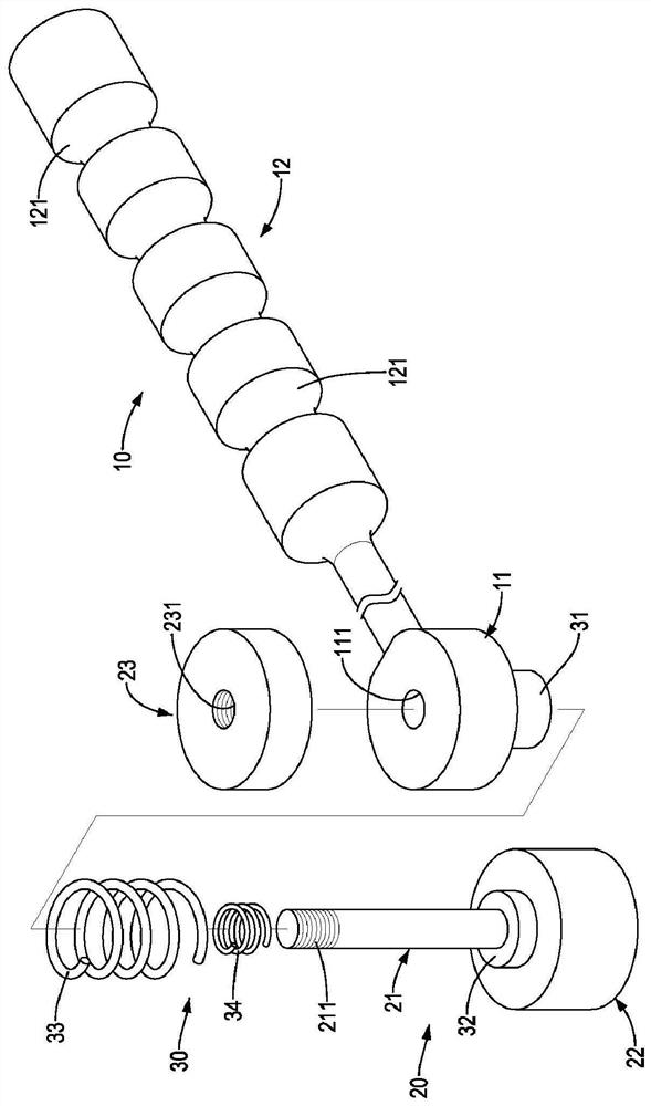
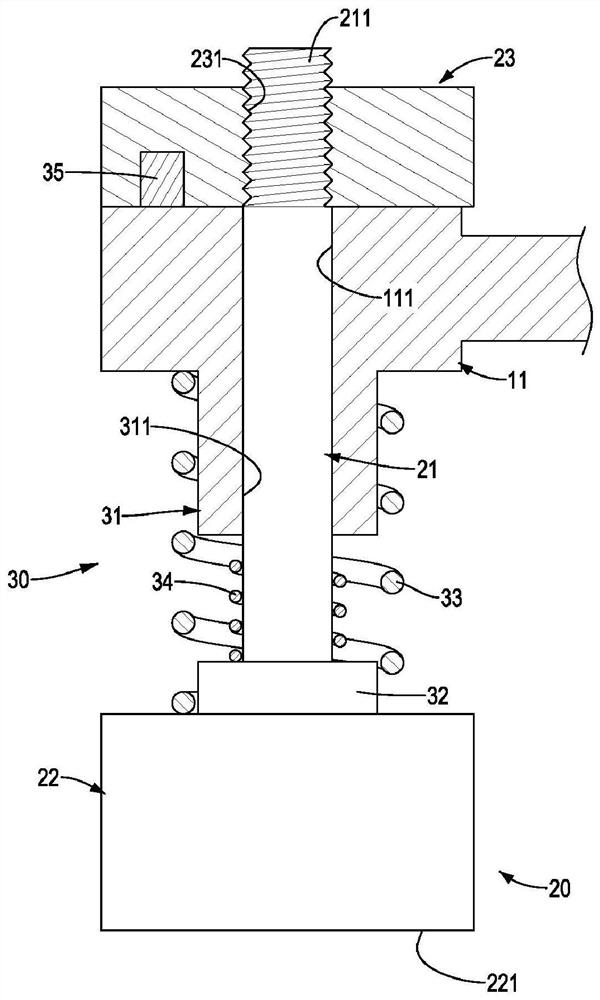
[0048] The present invention is a force-limiting shock-absorbing device, please refer to Figure 1 to Figure 3 In the first preferred embodiment shown, the force-limiting and shock-absorbing device is provided with a body 10, a knocker 20 and a force-limiting group 30, wherein:
[0049] The main body 10 is a strip-shaped metal rod body. The main body 10 is provided with a joint portion 11 at one end, and a set of holes 111 is formed axially through the joint portion 11 . There is a grip portion 12, further, the grip portion 12 is provided with an anti-skid structure on the outer surface, preferably, the anti-skid structure is a plurality of annular grooves 121 recessed on the outer surface of the grip porti...
PUM
 Abstract
Description
Claims
Application Information
 - R&D
- Intellectual Property
- Life Sciences
- Materials
- Tech Scout
- Unparalleled Data Quality
- Higher Quality Content
- 60% Fewer Hallucinations
Browse by: Latest US Patents, China's latest patents, Technical Efficacy Thesaurus, Application Domain, Technology Topic, Popular Technical Reports.
© 2025 PatSnap. All rights reserved.Legal|Privacy policy|Modern Slavery Act Transparency Statement|Sitemap|About US| Contact US: help@patsnap.com