Stabilized soil stirring plant

A mixing station and soil stabilization technology, applied in mixing plants, cement mixing devices, clay preparation devices, etc., can solve problems such as low mixing efficiency, long mixing time, and easy falling of raw materials

Inactive Publication Date: 2021-03-26
SHANDONG SHUNPENG BUILDING MATERIALS CO LTD
View PDF0 Cites 0 Cited by
  • Summary
  • Abstract
  • Description
  • Claims
  • Application Information

AI Technical Summary

Problems solved by technology

[0003] However, when the existing stabilized soil mixing station is in use, it cannot be automatically batched according to the proportion. Moreover, when the existing stabilized soil mixing station is used to transport the ingredients, due to the use of ordinary conveying rollers, the raw materials are easy to fall during lifting and transportation. Moreover, the existing stabilized soil mixing station has the disadvantage of low mixing efficiency and long mixing time when mixing the proportioned materials

Method used


Image

  • Stabilized soil stirring plant
  • Stabilized soil stirring plant
  • Stabilized soil stirring plant

Examples


Embodiment 1

[0030] Such as figure 1 , figure 2 , image 3 , Figure 4 , Figure 5 , Figure 6 , Figure 7 and Figure 8 shown;

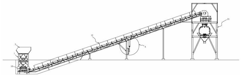
[0031] figure 1 It is a schematic diagram of the overall structure of the present invention;

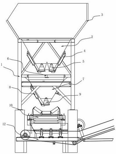
[0032] figure 2 It is a schematic diagram of the installation structure of the first bracket and the aggregate storage bucket in the present invention;

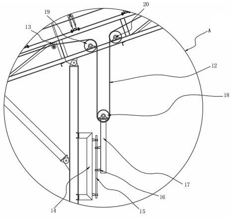
[0033] image 3 for the present invention figure 1 Schematic diagram of the structure at A;

[0034] Figure 4 It is a schematic diagram of the installation structure of the first support and the conveyor belt conveyor in the present invention;

[0035] Figure 5 It is a schematic diagram of the installation structure of the control room and the second support in the present invention;

[0036] Figure 6 It is a schematic diagram of the cross-sectional installation structure of the housing and the motor protection case in the present invention;

[0037] Figure 7 for the present invention Figure...


PUM


Abstract

The invention belongs to the technical field of stabilized soil stirring, and particularly relates to a stabilized soil stirring station. The station comprises a first support, the two-thirds positionof the bottom of the first support is buried underground, aggregate storage hoppers are installed on the first support, and the left end of the outer side of each aggregate storage hopper and the right end of the outer side of each aggregate storage hopper are rotationally connected with first air cylinders through rotating shafts; and the telescopic ends of the first air cylinders are rotationally connected with first closing doors through rotating shafts, the first closing doors are rotationally connected with the aggregate storage hoppers through rotating shafts, the first air cylinders and the first closing doors form closing mechanisms of the aggregate storage hoppers, and two sets of closing mechanisms are arranged on each aggregate storage hopper. When the device is used, a first nucleon scale is mounted on each group of aggregate storage and release mechanisms, so that a user can set the single release amount of each group of aggregate storage and release mechanisms in advancethrough a control room, and the proportioning of different aggregates can be automatically completed.

Description

technical field [0001] The invention belongs to the technical field of stabilized soil mixing, and in particular relates to a stabilized soil mixing station. Background technique [0002] Stabilized soil mixing plant is one of the important models of road construction machinery. The so-called stabilized soil mixing plant is a special production equipment that uniformly mixes materials such as soil, crushed stone, gravel, cement, fly ash, lime and water at a fixed location according to the construction mix ratio. [0003] However, when the existing stabilized soil mixing station is in use, it cannot be automatically batched according to the proportion. Moreover, when the existing stabilized soil mixing station is used to transport the ingredients, due to the use of ordinary conveying rollers, the raw materials are easy to fall during lifting and transportation. Moreover, the existing stabilized soil mixing station has the disadvantage of low mixing efficiency and long mixing...

Claims


Application Information

Patent Timeline
Patent Type & Authority Applications(China)
IPC IPC(8): B28C9/02B28C7/06B28C5/16
CPCB28C9/02B28C7/067B28C7/0481B28C5/16
Inventor 贾倩
Owner SHANDONG SHUNPENG BUILDING MATERIALS CO LTD
Why Eureka
Try Eureka