Stator structure and manufacturing method thereof
A stator structure and stator punching technology, which is applied in the manufacture of motor generators, stator/rotor bodies, magnetic circuit shapes/styles/structures, etc., can solve problems such as reducing the size of the motor and limited space for multi-pole windings, and achieve material The effect of small consumption, less winding waste, and low heat generation
- Summary
- Abstract
- Description
- Claims
- Application Information
AI Technical Summary
Problems solved by technology
Method used
Image
Examples
Embodiment 1
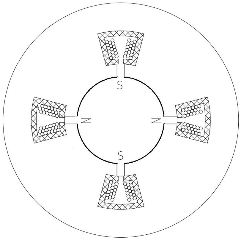
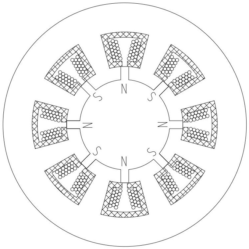
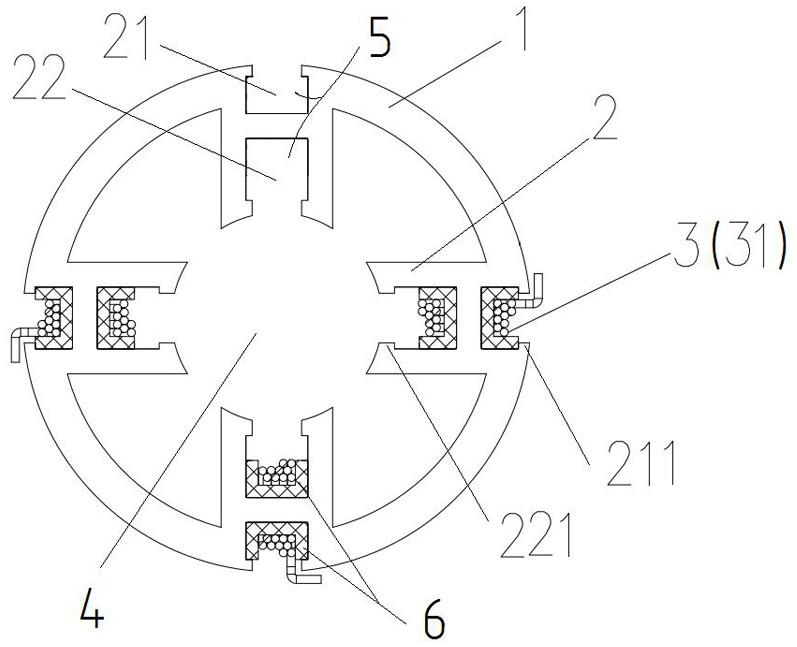
[0030] A stator structure such as image 3 As shown, it includes a yoke 1 and four teeth 2 distributed symmetrically along the center of the yoke 1, the teeth 2 are H-shaped structure teeth 2 arranged along the radial direction of the yoke 1, one of the The outer slot hole 21 and the inner slot hole 22 of the H-shaped tooth 2 jointly form a wire slot 5 for the winding coil 31 . Wires are respectively wound in the wire groove 5 formed by the outer slot 21 and the inner slot 22 of each H-shaped structure tooth 2 to form a motor winding 3, that is, a winding coil 31 is wound on an H-shaped structure tooth 2, The four winding coils 31 together form the motor winding 3. When the motor winding 3 is energized, the spatial position of an H-shaped structure tooth 2 forms two magnetic poles N and S tangential to the circumference of the stator structure; that is, when the yoke 1 has four When the tooth part 2 (H-shaped structure teeth), can generate 8 magnetic poles, it can obtain the ...
Embodiment 2
[0036] A manufacturing method of the above-mentioned stator structure includes the steps of punching out H-shaped structural teeth 2 on a cylindrical body or a plate body with a full circular structure, or directly casting them.
[0037] After forming, it is preferable to insert the plug-in type insulating card 6 relatively along its axial direction in the outer slot hole 21 and the inner slot hole 22 of each H-shaped structure tooth 2, and then insert the plug-in type insulating card 6 in the ring shape of each said plug-in type insulating card 6. A winding is wound in the slot along the axial direction of the stator structure; finally, each winding coil is welded to a corresponding position of the control board.
Embodiment 3
[0039] Different from the above-mentioned embodiments, the stator structure includes a plurality of stator punching pieces stacked on each other along the axial direction of the stator structure, and each stator punching piece includes the yoke portion 1 and the tooth portion 2 , the H-shaped structure teeth 2 of each of the stator punches are correspondingly overlapped to form a wire slot 5 .
[0040] A manufacturing method of the above-mentioned stator structure, comprising the steps of punching out the H-shaped structure teeth 2 and the yoke 1 on a thin sheet with a full circular structure (such as a silicon steel sheet) to form a stator punch; multiple pieces of the same shape The stator punching pieces are stacked, and the H-shaped structure teeth 2 of each stator punching piece are placed on top of each other, and then inserted into the outer slot hole 21 and the inner slot hole 22 of the H-shaped structure tooth 2 along its axial direction. Behind the plug-in insulation...
PUM
 Abstract
Description
Claims
Application Information
 - R&D
- Intellectual Property
- Life Sciences
- Materials
- Tech Scout
- Unparalleled Data Quality
- Higher Quality Content
- 60% Fewer Hallucinations
Browse by: Latest US Patents, China's latest patents, Technical Efficacy Thesaurus, Application Domain, Technology Topic, Popular Technical Reports.
© 2025 PatSnap. All rights reserved.Legal|Privacy policy|Modern Slavery Act Transparency Statement|Sitemap|About US| Contact US: help@patsnap.com


