
Apparatus and method for controlling resonance suppression of machine tool

A technology for suppressing control, machine tools, applied in motor control, program control, program control in sequence/logic controllers, etc., can solve the decline in accuracy and reliability, reduction in machine tool processing precision and reliability, and increase in manufacturing costs and other problems, to achieve the effect of improving precision and reliability, improving space utilization rate, and saving manufacturing costs

Pending Publication Date: 2021-03-26
DN SOLUTIONS CO LTD
View PDF0 Cites 0 Cited by
  • Summary
  • Abstract
  • Description
  • Claims
  • Application Information

AI Technical Summary

Problems solved by technology

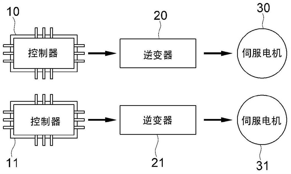
[0018] The first is an attenuation control device and method using an auxiliary inverter and an auxiliary winding, which additionally has a main inverter and an auxiliary inverter to form a structure of a servo motor and an auxiliary winding. However, there are still problems such as increased manufacturing costs and difficulty in mass production
[0019] The second type is an active damping control device and method, which only sets the resonance suppression control through empirical methods, thus cannot flexibly deal with actual resonance generation or many disturbances or variables, and has always been unable to ensure that the servo control device Reliability and stability, only the problem of increased manufacturing costs
[0020] The third type is a vibration reduction device and method using a load oscillation analyzer. It calculates the resonance suppression control by an empirical method, and requires a sensor capable of sensing the vibration phenomenon of the magnetic axis current, thereby increasing the manufacturing cost. increase, and the resonance suppression control is performed without considering the actual resonance generation or the real-time change caused by the operating state of the device, resulting in a significant decrease in accuracy and reliability, and ultimately has the problem of reduced machining precision and reliability of the machine tool

Method used


Image

  • Apparatus and method for controlling resonance suppression of machine tool
  • Apparatus and method for controlling resonance suppression of machine tool
  • Apparatus and method for controlling resonance suppression of machine tool

Examples


Embodiment Construction

[0044] A resonance suppression control device and a resonance suppression control method for a machine tool according to an embodiment of the present invention will be described in detail below with reference to the drawings. The embodiments described below are provided as examples in order to fully convey the idea of ​​the present invention to those skilled in the art. Therefore, the present invention is not limited to the Examples described below, and may be embodied in other forms. In addition, in the drawings, the size, thickness, etc. of the device may be shown exaggeratedly for convenience. Throughout the specification, the same reference numerals denote the same constituent elements.

[0045] The advantages, features and methods for achieving the present invention can be combined with the attached Figure 1 It will be clarified by referring to the embodiments described in detail later. However, the present invention is not limited to the embodiments disclosed below, ...


PUM


Abstract

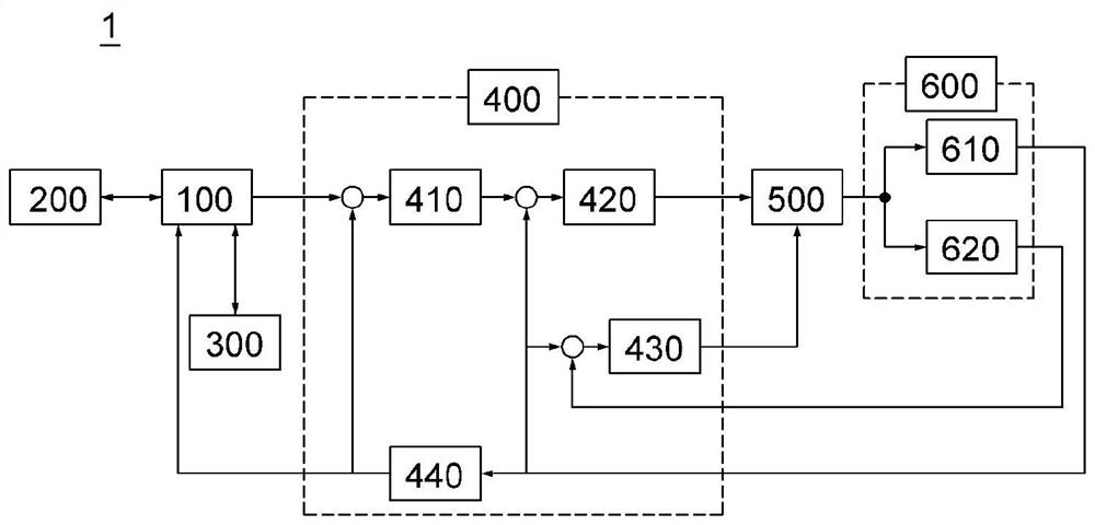
An apparatus for controlling resonance suppression of a machine tool according to the present invention, comprises: a numerical control part; a main operation part; a PLC for executing a control command by means of communication with the numerical control part or the main operation part; a servo drive for executing the control command of the PLC; a servo motor part driven under the control of theservo drive; and a power conversion part for applying electric energy to the servo motor part by being electrically connected to the servo motor part and the servo drive, wherein the power conversionpart adjusts the electric energy applied to the servo motor part according to a signal from the servo drive so as to control resonance suppression according to the operation of the servo motor part.

Description

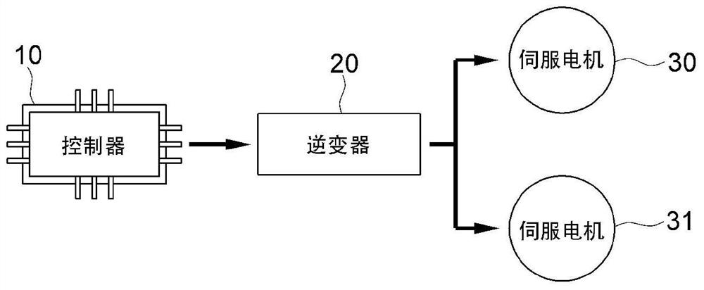
technical field [0001] The present invention relates to a resonance suppression control device and a resonance suppression control method of a machine tool. More specifically, it relates to transmitting an invalid torque command to a power conversion part through a resonance suppression control part, thereby adjusting the torque to the first servo motor and the second servo motor in the power conversion part. The electric energy applied by the two servo motors can suppress the resonance generated when the two servo motors run in parallel through a power conversion unit and a servo driver, thereby improving the stability and reliability of the machine tool and saving manufacturing and maintenance costs. A resonance suppressing control device and a resonance suppressing control method for a machine tool capable of achieving miniaturization. Background technique [0002] Generally, a machine tool refers to a machine used for the purpose of processing metal / non-metal workpieces ...

Claims


Application Information

Patent Timeline
Patent Type & Authority Applications(China)
IPC IPC(8): H02P29/00H02P5/46B23Q11/00
CPCB23Q11/00H02P29/50G05B19/404G05B2219/41122G05B2219/49176H02P29/00H02P5/46B23Q11/0032G05B19/05G05B2219/1185
Inventor 尹喆
Owner DN SOLUTIONS CO LTD
Learn More