Efficient automatic rotary hydraulic casting machining device

A processing device and hydraulic technology, used in positioning devices, metal processing equipment, metal processing mechanical parts, etc., can solve the problem of not being able to change the distance of the fixture

Inactive Publication Date: 2021-03-30
温州樱西机械科技有限公司
View PDF10 Cites 1 Cited by
  • Summary
  • Abstract
  • Description
  • Claims
  • Application Information

AI Technical Summary

Problems solved by technology

[0004] The purpose of the present invention is to provide a high-efficiency automatic rotary hydraulic casting processing device to solve the problem that the existing device proposed in the background technology cannot change the distance between the clamps and has limitations when working.

Method used


Image

  • Efficient automatic rotary hydraulic casting machining device
  • Efficient automatic rotary hydraulic casting machining device
  • Efficient automatic rotary hydraulic casting machining device

Examples


Embodiment 1

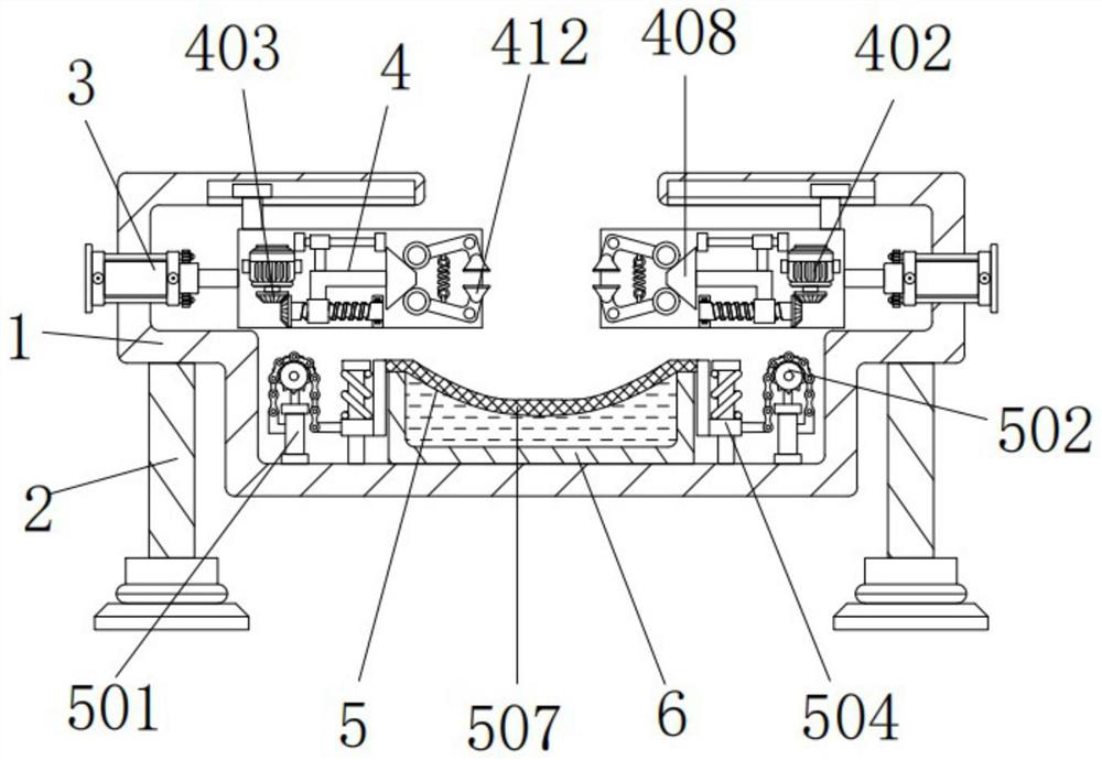
[0030] A high-efficiency automatic rotary hydraulic casting processing device, including a shell 1, a pillar 2 and a rotary hydraulic cylinder 3, two pillars 2 are arranged under the shell 1, and the tops of the two pillars 2 are connected to the left and right sides of the bottom of the shell 1 Fixedly connected, the left and right sides of the housing 1 are provided with rotary hydraulic cylinders 3 , and the outer walls of the two rotary hydraulic cylinders 3 are fixedly connected with the inner walls of the left and right sides of the housing 1 .

Embodiment 2

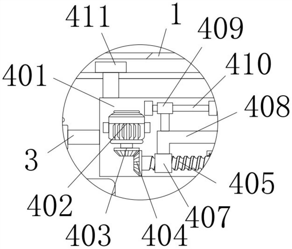
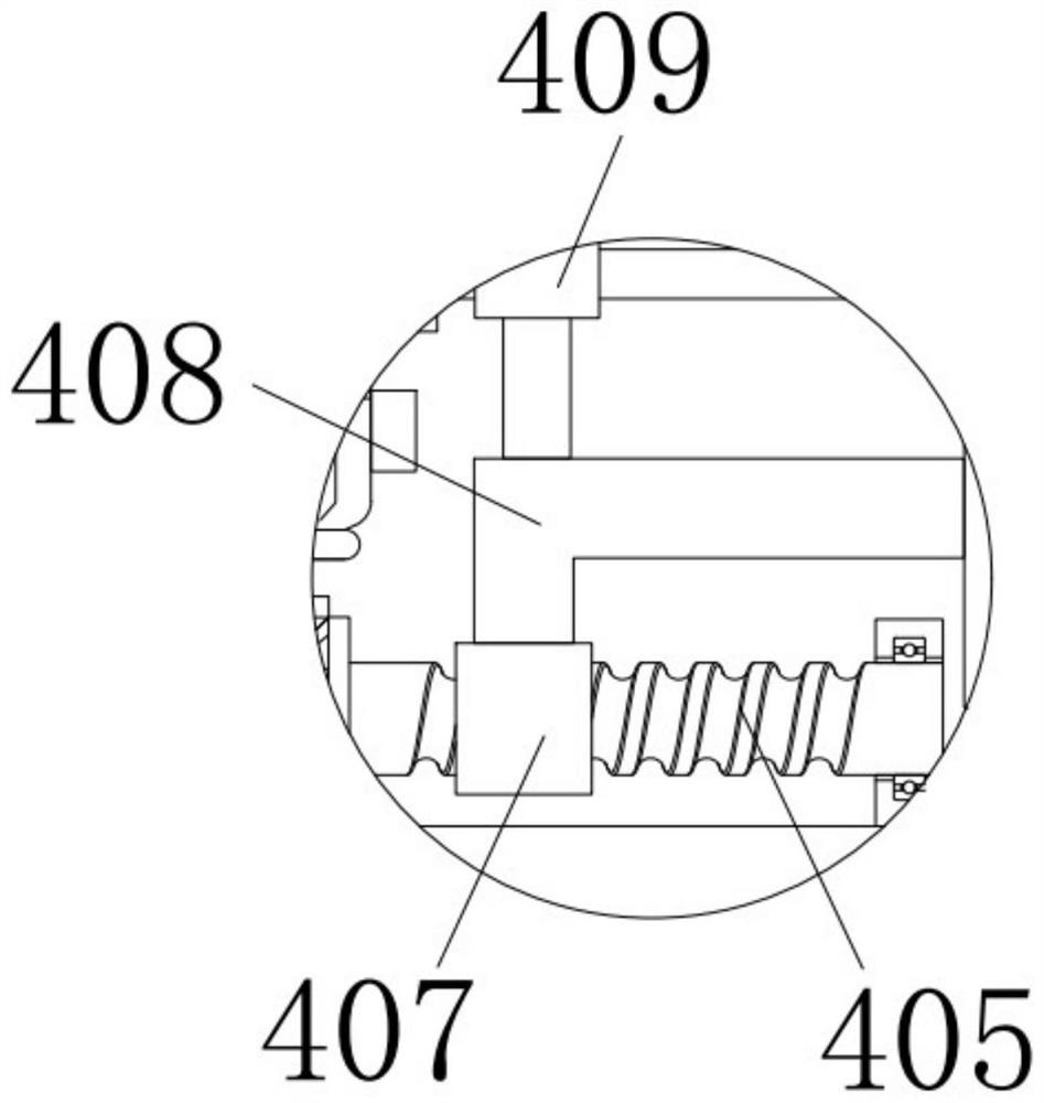
[0032] As an option, see Figure 1-4, high-efficiency automatic rotary hydraulic casting processing device, the interior of the housing 1 is provided with two fixing devices 4, the fixing device 4 includes a square plate 401, a motor 402, a first bevel gear 403, a second bevel gear 404, a screw 405, First spring 406, sleeve 407, straight rod 408, first sliding sleeve 409, first slide bar 410, slide block 411 and curved plate 412, the left side of square plate 401 and the right side of the rotary hydraulic oil cylinder 3 of left side are fixed connection, a slider 411 is provided above the square plate 401, the bottom of the slider 411 is fixedly connected to the top left side of the square plate 401, the outer wall of the slider 411 is slidably engaged with the groove on the left side of the inner wall top of the housing 1, and the sliding The block 411 can move in the groove on the left side of the inner wall top of the housing 1, the front of the square plate 401 is provided...

Embodiment 3

[0035] As an option, see figure 1 , 5 And 6, high-efficiency automatic rotary hydraulic casting processing device, the bottom of the inner wall of the housing 1 is provided with two filter devices 5, and the filter device 5 includes an electric push rod 501, a gear 502, a chain 503, a second sliding sleeve 504, and a second sliding rod 505, the second spring 506 and the filter screen 507, the bottom of the electric push rod 501 is fixedly connected with the bottom of the inner wall of the housing 1, the model of the electric push rod 501 is TG-700, and the top of the electric push rod 501 is connected through the rotation of the pin shaft. The gear 502 is meshed with a chain 503 above the gear 502, the left side of the chain 503 is fixedly connected with the left side of the electric push rod 501, the right side of the chain 503 is fixedly connected with a second sliding sleeve 504, and the inner wall of the second sliding sleeve 504 A second sliding rod 505 is slidingly clam...


PUM


Abstract

The invention discloses an efficient automatic rotary hydraulic casting machining device which comprises a shell, a supporting column and a rotary hydraulic oil cylinder. A first sliding rod is arranged on the inner wall of a first sliding sleeve; the outer wall of the first sliding rod is slidably connected with the inner wall of the first sliding sleeve in a clamped mode; the back face of the first sliding rod is fixedly connected with the upper part of the front face of a square plate; two bent plates are arranged on the right side of a straight rod; the left sides of the two bent plates are attached to the right side of the outer wall of the straight rod; a first spring is arranged on the right side of the straight rod; the upper end and the lower end of the first spring are fixedly connected with the inner sides of the two bent plates correspondingly; and the outer sides of the two bent plates are rotatably connected with the right side of the front face of the square plate through pin shafts. According to the device, through cooperation of a motor, the square plate and a screw rod, a user changes the distance between clamps by controlling the rotary hydraulic oil cylinder, the problem that the distance between the clamps cannot be changed when an existing device works is solved, and limitation does not exist.

Description

technical field [0001] The invention relates to the technical field of casting processing devices, in particular to a high-efficiency automatic rotary hydraulic casting processing device. Background technique [0002] Castings are metal shaped objects obtained by various casting methods, that is, the smelted liquid metal is poured into the pre-prepared mold by pouring, injection, suction or other casting methods, and after cooling, it is polished and other subsequent processing methods , the obtained objects with a certain shape, size and performance need to be processed again later. [0003] However, the existing device cannot change the distance between the clamps when working, which has limitations, and the existing device cannot collect the cutting fluid when working, which reduces the practicability. Contents of the invention [0004] The purpose of the present invention is to provide a high-efficiency automatic rotary hydraulic casting processing device to solve the...

Claims


Application Information

Patent Timeline
Patent Type & Authority Applications(China)
IPC IPC(8): B23Q3/08B23Q11/10
CPCB23Q3/082B23Q11/1069
Inventor 张志平
Owner 温州樱西机械科技有限公司
Why Eureka
Try Eureka