Polishing equipment and working method thereof

A technology of equipment and grinding wheels, which is applied in the direction of grinding/polishing equipment, metal processing equipment, grinding machines, etc., can solve problems such as large vibration and noise, reduced work efficiency, and high production cost, so as to reduce vibration and noise and ensure stability performance and production cost reduction

Active Publication Date: 2021-03-30
杭州龙砺智能科技有限公司
View PDF6 Cites 13 Cited by
  • Summary
  • Abstract
  • Description
  • Claims
  • Application Information

AI Technical Summary

Problems solved by technology

[0002] In the processing of workpieces, it is often necessary to polish the formed workpieces. Grinding equipment is often used to realize the grinding of workpieces. The grinding equipment includes manipulators, abrasive belt machines, material tables and control cabinets. In the prior art, grinding equipment The layout of the machine is unreasonable, resulting in reduced work efficiency and unsatisfactory grinding effect. Since most bases are made of steel, there will be large vibration and noise during operation. At the same time, the structure of the table driving device is relatively complicated and the production cost is high.
[0003] In view of this, a fully automatic manipulator belt sander is disclosed in the patent document with application number 201721740056.6. Its loading and unloading method is different from this application, and the vibration and noise generated during operation are relatively large, and the production cost Higher; in view of this, in the application number 201720313547.6 an industrial robot grinding and polishing workstation based on offline programming, its overall layout is different from this application

Method used


Image

  • Polishing equipment and working method thereof
  • Polishing equipment and working method thereof
  • Polishing equipment and working method thereof

Examples


Embodiment

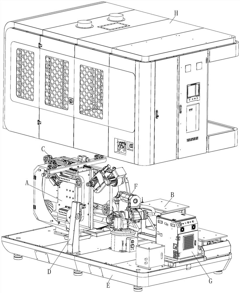
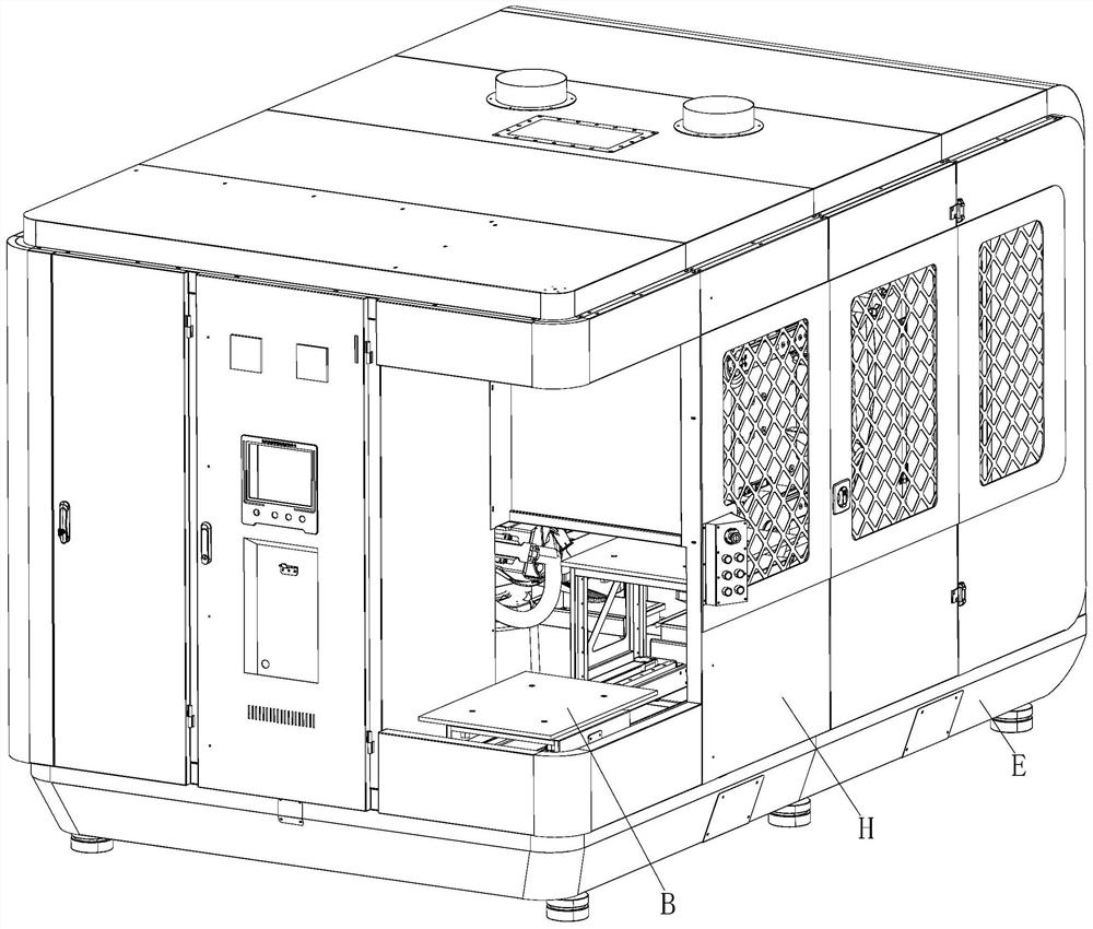
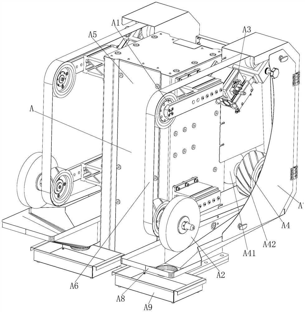
[0036] see Figure 1 to Figure 12 It should be noted that the structures, proportions, sizes, etc. shown in the drawings attached to this specification are only used to match the content disclosed in the specification, for those who are familiar with this technology to understand and read, and are not used to limit the present invention Therefore, it has no technical substantive meaning, and any modification of structure, change of proportional relationship or adjustment of size shall still fall into the within the scope covered by the technical content disclosed in the present invention. At the same time, if there are terms such as "upper", "lower", "left", "right", "middle" and "one" in this specification, they are only for the convenience of description and are not used to limit the scope of this specification. The practicable scope of the invention and the change or adjustment of its relative relationship shall also be regarded as the practicable scope of the present inve...


PUM


Abstract

The invention relates to polishing equipment and a working method thereof, and belongs to the field of mechanical equipment. The problems that the polishing equipment in the prior art is unreasonablein layout, so that the work efficiency is reduced, the polishing effect is not ideal, most of bases are made of steel, large vibration and noise are generated in the operation process, meanwhile, thestructure of a material table driving device is relatively complex and the production cost is high are solved. The polishing equipment comprises a manipulator, a control cabinet and an equipment outercover, and is structurally characterized in that a belt sander, a double-layer material table and an equipment base are further included, the belt sander, the manipulator and the control cabinet areall located in the equipment outer cover, the belt sander and the double-layer material table are both matched with the manipulator, and the belt sander, the double-layer material table, the manipulator, the control cabinet and the equipment outer cover are all installed on the equipment base. According to the polishing equipment and working method thereof, programs are set through the control cabinet, and workpieces located on the double-layer material table are placed on the belt sander through the manipulator to be polished.

Description

technical field [0001] The invention relates to a grinding device and a working method thereof, belonging to the field of mechanical equipment. Background technique [0002] In the processing of workpieces, it is often necessary to polish the formed workpieces. Grinding equipment is often used to realize the grinding of workpieces. The grinding equipment includes manipulators, abrasive belt machines, material tables and control cabinets. In the prior art, grinding equipment The layout of the machine is unreasonable, resulting in reduced work efficiency and unsatisfactory grinding effect. Since most bases are made of steel, large vibration and noise will be generated during operation. At the same time, the structure of the table driving device is relatively complicated and the production cost is high. [0003] In view of this, a fully automatic manipulator belt sander is disclosed in the patent document with application number 201721740056.6. Its loading and unloading method ...

Claims


Application Information

Patent Timeline
Patent Type & Authority Applications(China)
IPC IPC(8): B24B21/00B24B21/18B24B21/20B24B1/00
CPCB24B21/008B24B21/18B24B21/20B24B1/00
Inventor 金忠豪
Owner 杭州龙砺智能科技有限公司
Why Eureka
Try Eureka