
Continuous dynamic membrane system operation device and working method thereof

An operating device and dynamic membrane technology, applied in chemical instruments and methods, special treatment targets, water treatment parameter control, etc., can solve problems such as multi-dissolved gas and recirculation steps, long intermittent operation time, long aeration time, etc. Achieve the effects of reducing aeration intensity and aeration time, improving filtration time and operating efficiency, and reducing operating energy costs

Pending Publication Date: 2021-03-30
NANJING UNIV OF INFORMATION SCI & TECH
View PDF5 Cites 0 Cited by
  • Summary
  • Abstract
  • Description
  • Claims
  • Application Information

AI Technical Summary

Problems solved by technology

Air washing is to install an aeration system under the membrane module to achieve the effect of scouring and cleaning the dynamic membrane through aeration to slow down the membrane fouling, but the aeration time is longer, which prolongs the cleaning time of the system
Some device systems use continuous aeration to delay membrane fouling, which obviously consumes a lot of energy
Off-line water washing is to take out the clogged membrane module and directly flush it with high-pressure water to remove membrane pollution. The process is more complicated and the intermittent time is long.
For example, a dynamic membrane water treatment device has been reported in the patent No. CN2403733Y. The invention is provided with a dissolved air tank and a recirculation reflux tank to slow down membrane fouling by releasing the dissolved air in the sewage to make the filter cake loose, but There are more steps of dissolving gas and circulating reflux, the operation interval is long, and the operation is complicated
Patent CN1843971A reports a backwashing operation method of a dynamic membrane bioreactor. This invention adopts an uninterrupted aeration method, which slows down the formation rate of the dynamic membrane, but the intermittent operation time is long and the power consumption is large.

Method used


Image

  • Continuous dynamic membrane system operation device and working method thereof

Examples


Embodiment Construction

[0035] The present invention is described in further detail now in conjunction with accompanying drawing.

[0036] It should be noted that terms such as "upper", "lower", "left", "right", "front", and "rear" quoted in the invention are only for clarity of description, not for Limiting the practicable scope of the present invention, and the change or adjustment of the relative relationship shall also be regarded as the practicable scope of the present invention without substantive changes in the technical content.

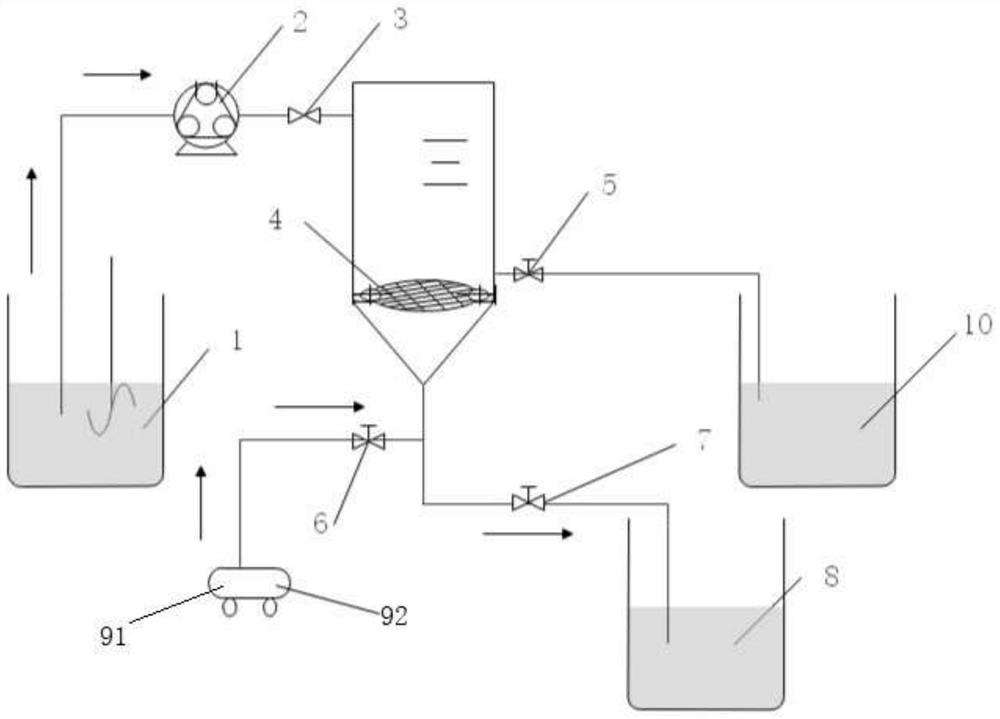
[0037] combine figure 1 , the present invention refers to a continuous dynamic membrane system operating device, the operating device is installed on the dynamic membrane filtration system, including supporting membrane 4, water inlet and sump 1, peristaltic pump 2, water inlet 3, water outlet 7, water outlet Water tank 8, backwash water pump 92, backwash air pump 91, backwash water inlet 6, backwash water outlet 5, backwash sump 10, pressure sensor and processor. ...


PUM


Abstract

The invention discloses a continuous dynamic membrane system operation device, which comprises a supporting membrane, a water inlet collecting tank, a peristaltic pump, a water inlet, a water outlet,a water outlet collecting tank, a backwashing water pump, a backwashing air pump, a backwashing water inlet, a backwashing water outlet, a backwashing water collecting tank, a pressure sensor and a processor; when the actual measurement pressure value exceeds a preset pressure value threshold value, the processor calculates according to the actual measurement pressure value and a preset pressure value standard value to obtain strength values and flushing duration of the backwashing water pump and the backwashing air pump; when the loosening value of the dynamic membrane layer above the supportmembrane reaches a preset condition, the loosening membrane layer is washed off by adopting a backwashing water pump to enable the error between the transmembrane pressure of the washed dynamic membrane and the standard value of the pressure value to be less than a preset error threshold value. The invention has the advantages of high backwashing efficiency and high dynamic membrane recovery speed, and indirectly enhances the operating efficiency of the whole dynamic membrane filtration system.

Description

technical field [0001] The invention relates to the technical field of water treatment, in particular to a continuous dynamic membrane system operating device and a working method thereof. Background technique [0002] Dynamic membrane filtration technology is an emerging membrane separation technology, which is mainly used in sewage treatment. The core of dynamic membrane filtration technology is the formation of a dynamic membrane layer. Its supporting membrane components are usually composed of cheap macroporous micro-network materials. By pre-coating or gradually trapping micro-particles or pre-coating materials in sewage on the supporting membrane, they gradually A dynamic film layer is formed to obtain a good separation effect. [0003] Dynamic membrane technology can be divided into three stages according to the change law of transmembrane pressure and effluent turbidity: formation stage, filtration stage and backwash stage. When the influent flow rate and influent ...

Claims


Application Information

Patent Timeline
IPC IPC(8): C02F1/44
CPCC02F1/44C02F2303/16C02F2209/03
Inventor 朱泽华李路程李思敏李睿李振炫沈亚飞
Owner NANJING UNIV OF INFORMATION SCI & TECH
Learn More