Wide-temperature-range gap compensation roller assembly with guiding, damping and supporting effects

A technology of vibration damping support and clearance compensation, applied in the direction of spring/shock absorber, vibration suppression adjustment, shaft and bearing, etc., can solve the influence of the transmission accuracy and transmission performance of the mechanism, cannot meet the mechanism clearance compensation, and the guide rail cannot be lubricated, etc. problems, to achieve the effect of no major changes in the guiding accuracy, improved motion adaptability, and compact structure

Inactive Publication Date: 2021-03-30
INST OF HIGH SPEED AERODYNAMICS OF CHINA AERODYNAMICS RES & DEV CENT
View PDF8 Cites 0 Cited by
  • Summary
  • Abstract
  • Description
  • Claims
  • Application Information

AI Technical Summary

Problems solved by technology

[0003] However, in some special occasions, such as a certain medium, the mechanism not only has the characteristics of fast speed, large load, and high frequency of use, but also works in a wide temperature range that continuously changes between ultra-low temperature and normal temperature. The structure caused by a large temperature difference Dimensional changes have a greater impact on the transmission accuracy and performance of the mechanism
Conventional guide devices, such as guide rails with balls as the power transmission interface, cannot be effectively lubricated at low temperatures, and are prone to jamming and seizure; conventional roller guide devices are fixed structures, which cannot meet the needs of the mechanism in uneven rise and fall. Gap compensation function in case of cooling

Method used


Image

  • Wide-temperature-range gap compensation roller assembly with guiding, damping and supporting effects
  • Wide-temperature-range gap compensation roller assembly with guiding, damping and supporting effects
  • Wide-temperature-range gap compensation roller assembly with guiding, damping and supporting effects

Examples


Embodiment 1

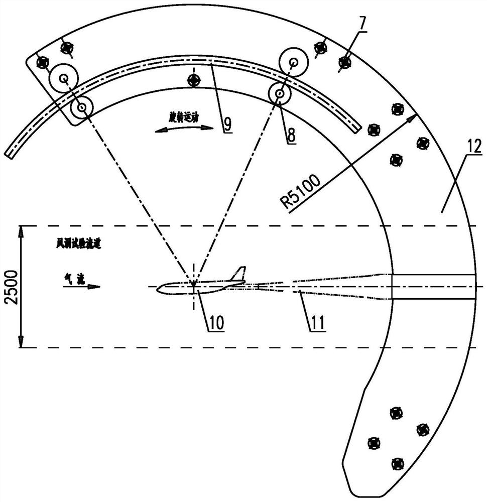
[0047] Such as image 3 As shown, multiple sets of roller assemblies 7 are installed on both sides of the arc-shaped support plate 12 of the wind tunnel, and the arc-shaped support plate 12 is pressed against the positioning roller assembly 2 and the pressing roller assembly 3, and the multiple sets of roller assemblies 7 reduce the Lateral swing of arc support plate 12. The radius of the arc guide rail 9 of this wind tunnel is 4000mm, and the test model 10 is installed on the rotation center of the arc guide rail 9, and the test model 10 is fixed on the arc support plate 12 through the tail support rod 11. When the arc support plate 12 When moving along the arc guide rail 9 under the action of the rotary guide assembly 8, the arc support plate 12 drives the angle of attack of the test model 10 to continuously change in a wide range, and the stroke of the rotary guide assembly 8 is 2100mm.

[0048] In a wide temperature range, the test model 10 was tested under different airf...


PUM


Abstract

The invention discloses a wide-temperature-range gap compensation roller assembly with guiding, damping and supporting effects. The roller assembly comprises a positioning roller assembly and a pressing roller assembly which are installed on the two sides of a supporting component and oppositely abut against the supporting component; the pressing roller assembly comprises a jacking wheel set and afixed guide assembly which are connected in a sliding mode through a guide sliding rod assembly, the fixed guide assembly is a fixed end, the jacking wheel set is a free end, and the jacking wheel set jacks the supporting component through a disc spring set installed in the circumferential direction of a guide screw; and the structure of the positioning roller assembly is similar to that of the pressing roller assembly, and the difference lies in that the disc spring set is replaced with a supporting guide sliding rod which is fixedly arranged on the guide screw in a sleeved mode and limits the moving distance of the guide screw. The roller assembly solves the problems of mechanism movement at low temperature and movement gap compensation, movement guide support and vibration reduction ofthe mechanism due to wide temperature range change, and ensures the guide precision of the mechanism in the movement process.

Description

technical field [0001] The invention belongs to the technical field of wind tunnel equipment, and in particular relates to a gap compensation roller assembly in a wide temperature range with the function of guiding, damping and supporting. Background technique [0002] In the process of mechanical engineering, guiding devices are often used during the movement of mechanisms. Conventional guiding devices are divided into linear guides and arc guides according to their functions, and sliding friction guides, rolling friction guides, and elastic friction guides according to their friction properties. type. Among them, the more widely used guide rail uses balls as the power transmission interface between the guide rail and the slider, which can perform infinite rolling cycle movement, and the slider is limited on the guide rail, so that the load device can move along the guide rail with high speed and high precision. For reciprocating linear motion. If the movement accuracy is...

Claims


Application Information

Patent Timeline
Patent Type & Authority Applications(China)
IPC IPC(8): F16F15/073F16C13/00
CPCF16F15/073F16C13/00
Inventor 鲍禄强马东平杨晓峰赵宽李多
Owner INST OF HIGH SPEED AERODYNAMICS OF CHINA AERODYNAMICS RES & DEV CENT
Why Eureka
Try Eureka