Agricultural stubble treatment device

A processing device and stubble technology, applied in the field of agricultural equipment, can solve problems such as unfavorable agricultural production, time-consuming and other problems, and achieve the effects of being beneficial to agricultural production, convenient for decay, and improving efficiency

Inactive Publication Date: 2021-04-02
秦松松
View PDF0 Cites 0 Cited by
  • Summary
  • Abstract
  • Description
  • Claims
  • Application Information

AI Technical Summary

Problems solved by technology

[0004] The invention provides an agricultural root stubble treatment device, which can solve the problem in the prior art that the processing method of farmland stubble is relatively primitive, and it takes a long time to rely on the natural rotting of root stubble to fertilize, which is not conducive to agricultural production.

Method used


Image

  • Agricultural stubble treatment device
  • Agricultural stubble treatment device
  • Agricultural stubble treatment device

Examples


Embodiment 1

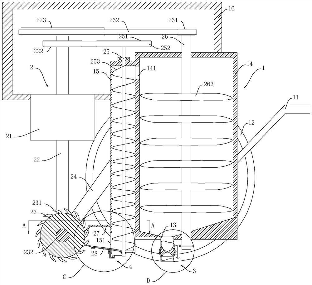
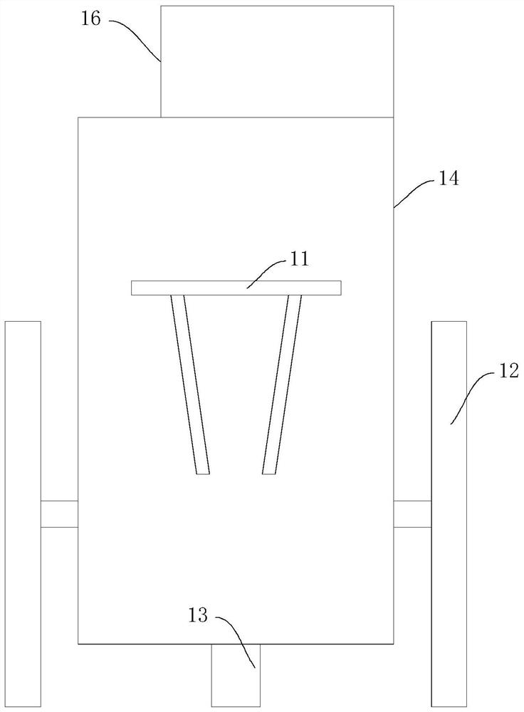
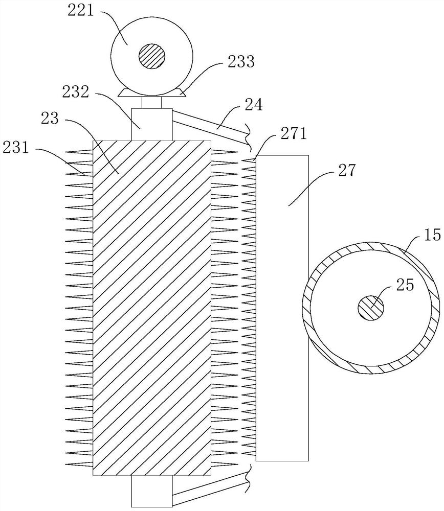
[0028] Such as Figure 1 to Figure 8 As shown, a kind of agricultural stubble processing device provided by the embodiment of the present invention includes a storage device 1 and a drive device 2, and the storage device 1 includes a handle 11, wheels 12, discharge pipe 13, storage barrel 14, and feeding barrel 15 And the housing 16, two wheels 12, the two wheels 12 are respectively rotatably connected to both sides of the material storage barrel 14, the handle 11 and the feeding barrel 15 are respectively fixedly connected to the other two sides of the material storage barrel 14, The side wall of the upper end of the material storage barrel 14 is provided with a feed inlet 141, and the feed inlet 141 penetrates into the material storage barrel 14 and the feed barrel 15 respectively, and the housing 16 is fixedly connected to the top of the material storage barrel 14, and the discharge pipe 13 is fixedly connected to the bottom of the storage tank 14, and the discharge pipe 13...

Embodiment 2

[0035] On the basis of Example 1, such as Figure 1 to Figure 8 As shown, the bottom end of the storage tank 14 is provided with a blanking device 3, and the blanking device 3 includes a blanking ball 31, a first connecting rod 32, a rotating disk 33, a ring gear 34, a second connecting rod 35, a block 36 and The locking block 37 and the blanking ball 31 are rotatably arranged in the discharge pipe 13, the upper and lower ends of the blanking ball 31 are provided with a spherical blanking chamber 311, and one end of the first connecting rod 32 is connected to the discharge pipe 13 The inside is fixedly connected with the blanking ball 31, and the other end of the first connecting rod 32 is connected to the middle of the turntable 33 by transmission, and the two sides of the turntable 33 are fixedly connected with the first gear teeth 331 and the second gear teeth respectively along the circumferential direction. 332, the ring gear 34 is fixedly connected to the second drive sh...

Embodiment 3

[0038] On the basis of embodiment 1 or 2, such as Figure 1 to Figure 8 As shown, the lower end of the feeding bucket 15 is provided with a knocking device 4, and the knocking device 4 includes a housing case 41, an L-shaped rod 43, a third spring 44, a first impact ball 45, a second impact ball 46 and a third connection The rod 47 and the storage case 41 are fixedly connected to the lower surface of the second support plate 28. The storage case 41 is provided with a storage chamber 42. One end of the L-shaped rod 43 is slidably connected in the storage chamber 42, and the other end is fixedly connected The first impact ball 45, the third spring 44 is sleeved on one end of the L-shaped rod 43 located in the storage cavity 42, one end of the third spring 44 is fixedly connected to the L-shaped rod 43, and the other end is fixedly connected to the storage case 41 On the inner wall of the third connecting rod 47, one end of the third connecting rod 47 is fixedly connected to the ...


PUM


Abstract

The invention discloses an agricultural stubble treatment device, and belongs to the technical field of agricultural instruments. The device comprises a storage device and a driving device, wherein the storage device comprises a handle, two wheels, a discharging pipe, a storage barrel, a feeding barrel and a shell, the two wheels are rotatably connected to the two sides of the storage barrel correspondingly, and the handle and the feeding barrel are fixedly connected to the other two sides of the storage barrel correspondingly. The device has the following beneficial effects that stubbles in aturned farmland are conveyed into the feeding barrel through a picking roller, the stubbles in the feeding barrel are conveyed into the storage barrel through spiral blades, the stubbles are choppedthrough chopping blades, and the chopped stubbles fall into an external farmland through the discharging pipe; and the chopped stubbles are more easily rotten, the stubble water-logged compost efficiency is improved, agricultural production is facilitated, and farmland plant alteration is convenient due to quicker rotting.

Description

technical field [0001] The invention relates to the technical field of agricultural equipment, in particular to an agricultural stubble processing device. Background technique [0002] In agricultural production, plants can usually be divided into fruit parts and rhizome parts, and the rhizomes of most plants are difficult to use effectively. For these hard-to-use plant roots, people need to deal with them. Taking the common economic crop corn as an example, the root stubble of corn is a component of corn stalks. The yield ratio of corn seeds to root stubble is about 1:0.28. According to this ratio, the annual output of corn stubble in my country can reach 42 million tons. Every year after corn is harvested, corn root stubble will be left in the farmland, while the existing The treatment of root stubble in the technology is to directly turn over the farmland and leave the root stubble to rot and retting in the farmland. This method is extremely slow and is not conducive to ...

Claims


Application Information

Patent Timeline
Patent Type & Authority Applications(China)
IPC IPC(8): A01D82/00
CPCA01D82/00
Inventor 不公告发明人
Owner 秦松松
Why Eureka
Try Eureka