
Disposable automatic anorectal loop ligation gun

A one-time, automatic technology, applied in medical science, surgical cutting instruments, surgery, etc., can solve the problems of complex internal structure movement process, troublesome control, complex structure, etc., and achieve low operating force, low production cost, and low process requirements Effect

Pending Publication Date: 2021-04-02
微尔创(武汉)医疗科技有限公司
View PDF0 Cites 2 Cited by
  • Summary
  • Abstract
  • Description
  • Claims
  • Application Information

AI Technical Summary

Problems solved by technology

With the upgrading of equipment and material technology, people have developed many types of ligation devices. Among them, manual control ligation devices are low in cost, high in safety, and easy to use, and are welcomed by medical institutions at all levels. There are many ligation devices that use various mechanical drives and work, but due to the limitation of cost and material properties, the current manual ligation equipment either relies on manpower to drive the main process, which is flexible but slow and inefficient, or Use spring mechanism and small electronic equipment to complete the adsorption control. Although the speed is fast, the structure is complex and the cost is high. At the same time, the internal structure is relatively complicated relative to the movement process, and the control is relatively troublesome. It is easy to cause operation due to inaccurate alignment and other reasons. Failure, various reasons, lead to the fact that most of the current ligation tools have not been widely promoted and applied in various primary medical structures

Method used


Image

  • Disposable automatic anorectal loop ligation gun
  • Disposable automatic anorectal loop ligation gun
  • Disposable automatic anorectal loop ligation gun

Examples


Embodiment Construction

[0029] The present application will be described in detail below in conjunction with specific embodiments.

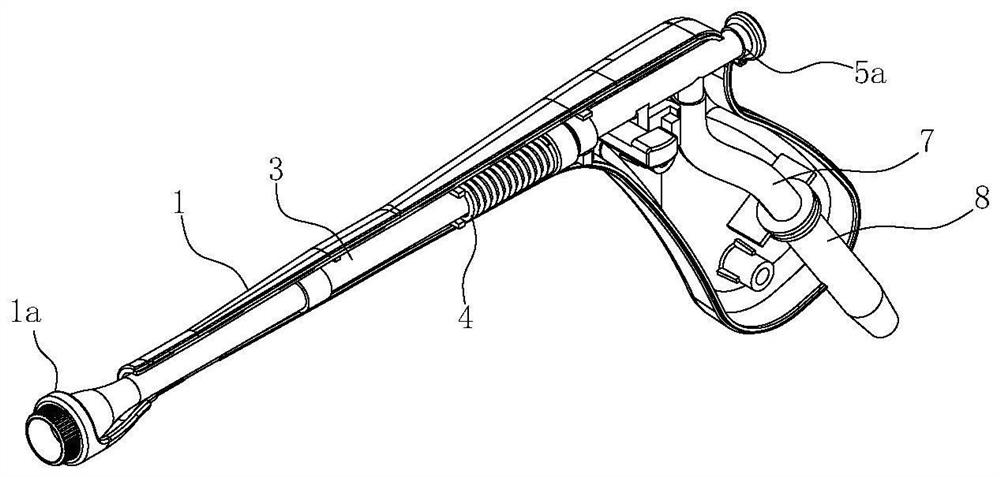
[0030] Such as Figure 1 to Figure 5 As shown, a kind of disposable automatic anorectal ligation gun of the present application is mainly used as a disposable appliance for anorectal ligation operation to assist doctors to complete the operation. Low-pressure adsorption airflow) to absorb the area to be ligated, and then put the ligation loop on the lower part of the adsorption area to complete the ligation.

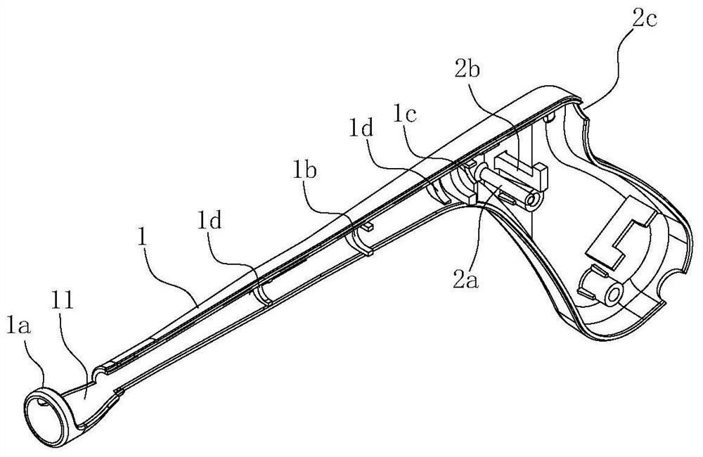
[0031] Such as figure 1 , Figure 5 As shown, its basic structure includes a gun casing provided with a barrel 1 and a handle 2, and also includes an adsorption component arranged in the gun casing; in this embodiment, the internal action of the banding gun has small impact, simple action, and has no impact on material properties. There is no special requirement, and it is generally made of medical polymer materials.

[0032] In order to facilitate processing ...


PUM


Abstract

The invention belongs to the technical field of medical auxiliary instruments and equipment, and particularly relates to a disposable automatic anorectal loop ligation gun. The disposable automatic anorectal loop ligation gun comprises a gun shell provided with a gun barrel and a grip, and further comprises an adsorption assembly arranged in the gun shell; the adsorption assembly comprises an adsorption pipe arranged in the gun shell, a first spring arranged at the rear end of the adsorption pipe in a sleeving mode, a push rod arranged on the rear side of the adsorption pipe, a switch piece arranged on the lower side of the push rod, a second spring arranged on a guide shaft in a sleeving mode and a third spring arranged between the push rod and the gun shell. According to the disposable automatic anorectal loop ligature gun, in the whole loop ligature process, only the adsorption pipe and the push rod slightly slide forwards and backwards, the switch piece slightly slides leftwards and rightwards, the relative movement amount in the whole process is small, the stroke is short, the operation force is small, convenience and labor saving are achieved in the operation process, the stress of a structural piece is small, thus the structure is more stable, the requirements of processing and production on material strength and the like and the process requirements during processing are low, and the production cost is low.

Description

technical field [0001] The application belongs to the technical field of medical auxiliary equipment, in particular to a disposable automatic anorectal ligation gun. Background technique [0002] Anorectal ligation device is a commonly used medical device for anorectal ligation operation, which can reduce medical operation time, operation difficulty and operation cost. With the upgrading of equipment and material technology, people have developed many types of ligation devices. Among them, manual control ligation devices are low in cost, high in safety, and easy to use, and are welcomed by medical institutions at all levels. There are many ligation devices that use various mechanical drives and work, but due to the limitation of cost and material properties, the current manual ligation equipment either relies on manpower to drive the main process, which is flexible but slow and inefficient, or Use spring mechanism and small electronic equipment to complete the adsorption co...

Claims


Application Information

Patent Timeline
IPC IPC(8): A61B17/12A61B17/3205
CPCA61B17/12009A61B17/32056A61B2017/12018
Inventor 肖军周慧敏熊军
Owner 微尔创(武汉)医疗科技有限公司
Learn More