Basic shaft type metal 3D printer

A 3D printer and base axis technology, applied in the direction of additive processing, etc., can solve the problems of unable to meet the processing symmetry of rotating parts, unable to guarantee the quality of printed products, uncontrolled temperature stress of workpieces, etc., to achieve a simple structure and improve the scope of application. , the effect of convenient printing

Pending Publication Date: 2021-04-02
ZHEJIANG YIDONG TECH CO LTD
View PDF8 Cites 1 Cited by
  • Summary
  • Abstract
  • Description
  • Claims
  • Application Information

AI Technical Summary

Problems solved by technology

[0007] 1. It is necessary to set up complex mechanism components such as powder spreading device and powder scraping device;
[0008] 2. It cannot meet the requirements of processing symmetry of some rotating parts;
[0009] 3. The quality of printed and processed products cannot be guaranteed, and the temperature and stress of the workpiece during printing are not controlled, which may easily cause defects such as stress concentration

Method used


Image

  • Basic shaft type metal 3D printer
  • Basic shaft type metal 3D printer
  • Basic shaft type metal 3D printer

Examples


Embodiment 1

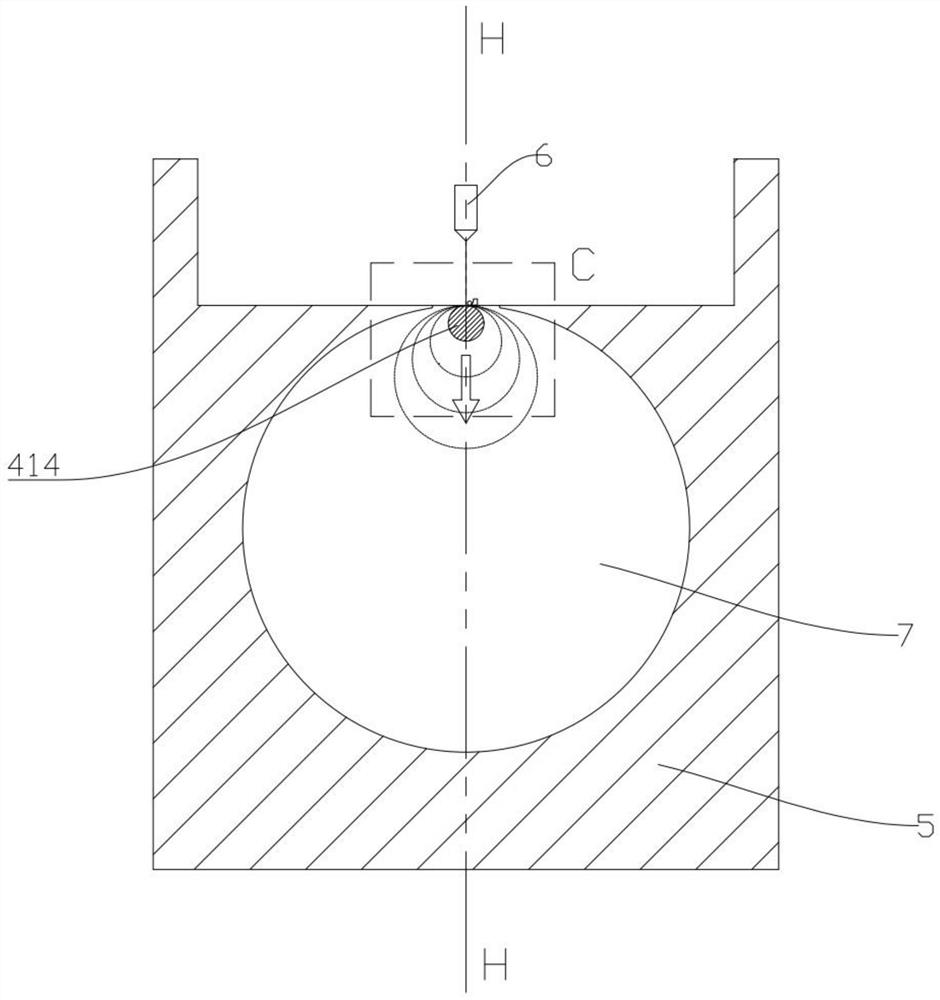
[0058] like Figures 1 to 7 As shown, a base-axis metal 3D printer includes a frame;

[0059] The middle part of the frame is provided with a powder cylinder;

[0060] The powder cylinder is cylindrical, and its extension direction is parallel to the horizontal plane;

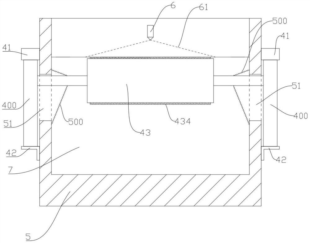
[0061] The upper part of the two outer side walls of the frame in the extending direction of the powder cylinder is detachably and fixedly connected with the two mounting plates of the base shaft drive device, respectively, and the lower part of the two outer side walls are respectively connected with the two fixed plates of the base shaft drive device. Remove the fixed connection;

[0062] An elongated limit through hole is correspondingly opened on an opposite side of the frame and the powder cylinder;

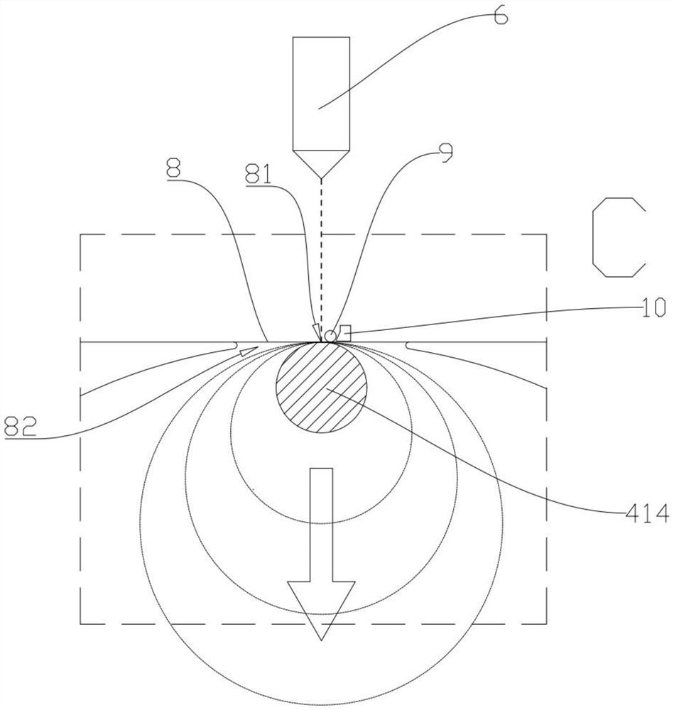
[0063] The base shaft driving device is used to drive the base shaft to rotate and / or move up and down;

[0064] The extension direction of the base shaft is the same as the extension direction of the pow...

Embodiment 2

[0073] like Figures 1 to 7 As shown, a base-axis metal 3D printer includes a frame;

[0074] The middle part of the frame is provided with a powder cylinder;

[0075] The powder cylinder is cylindrical, and its extension direction is parallel to the horizontal plane;

[0076] The upper part of the two outer side walls of the frame in the extending direction of the powder cylinder is detachably and fixedly connected with the two mounting plates of the base shaft drive device, respectively, and the lower part of the two outer side walls are respectively connected with the two fixed plates of the base shaft drive device. Remove the fixed connection;

[0077] An elongated limit through hole is correspondingly opened on an opposite side of the frame and the powder cylinder;

[0078] The base shaft driving device is used to drive the base shaft to rotate and / or move up and down;

[0079] The extension direction of the base shaft is the same as the extension direction of the pow...


PUM


Abstract

The invention discloses a base shaft type metal 3D printer. The base shaft type metal 3D printer comprises a machine frame, a powder cylinder is arranged in the middle of the machine frame, the machine frame is connected with a base shaft driving device, long-strip-shaped limiting through holes are correspondingly formed in the opposite sides of the machine frame and the powder cylinder, and a base shaft comprises a base shaft body and base shaft connecting shafts at the two ends; the base shaft is located in the powder cylinder, and the base shaft connecting shafts at the two ends of the baseshaft penetrate through the long-strip-shaped limiting through holes to be detachably and fixedly connected with the base shaft driving device; and sealing assemblies used for preventing metal powderin the powder cylinder from overflowing are arranged between the base shaft connecting shafts and the long-strip-shaped limiting through holes. The basic shaft type metal 3D printer is simple in structure and convenient to use, complex components such as a powder laying device and a powder scraping device are omitted, the requirements for machining symmetry and the like of some rotating components are well met, the quality of printed and machined products is guaranteed, and the temperature stress of workpieces in the printing process is controlled.

Description

technical field [0001] The invention relates to the technical field of 3D printing equipment, in particular to a base shaft type metal 3D printer. Background technique [0002] Metal 3D printers have the advantages of personalized design, rapid molding, and short manufacturing cycle. They are very suitable for the manufacture of small batches, personalized metal parts with complex surfaces and internal structures. In the process of 3D printing metal powders, high energy density The laser directly acts on the metal powder, and the laser scans rapidly, so that the metal powder is rapidly melted and then rapidly condensed. [0003] For example, Chinese patent application number: CN201910146552.6, discloses a metal 3D printer that is convenient for timely cooling, including a top plate, a support rod, a bottom fixing seat, an upper fixing seat, a first motor, a first screw rod, and a first rotating sleeve , the second motor, the second screw rod and the third motor, the bottom ...

Claims


Application Information

Patent Timeline
Patent Type & Authority Applications(China)
IPC IPC(8): B22F12/00B22F12/37B33Y30/00
CPCB33Y30/00
Inventor 韩品连
Owner ZHEJIANG YIDONG TECH CO LTD
Why Eureka
Try Eureka