Installation and detachment device and installation and detachment method of speed reducer for roller press
A dismantling device and reducer technology, which is applied in metal processing, metal processing equipment, hand-held tools, etc., can solve the problems of difficulty in installing and disassembling the reducer, and achieve the advantages of simple installation method and disassembly operation, simple structure, and guaranteed installation accuracy Effect
- Summary
- Abstract
- Description
- Claims
- Application Information
AI Technical Summary
Problems solved by technology
Method used
Image

Examples
Embodiment 1
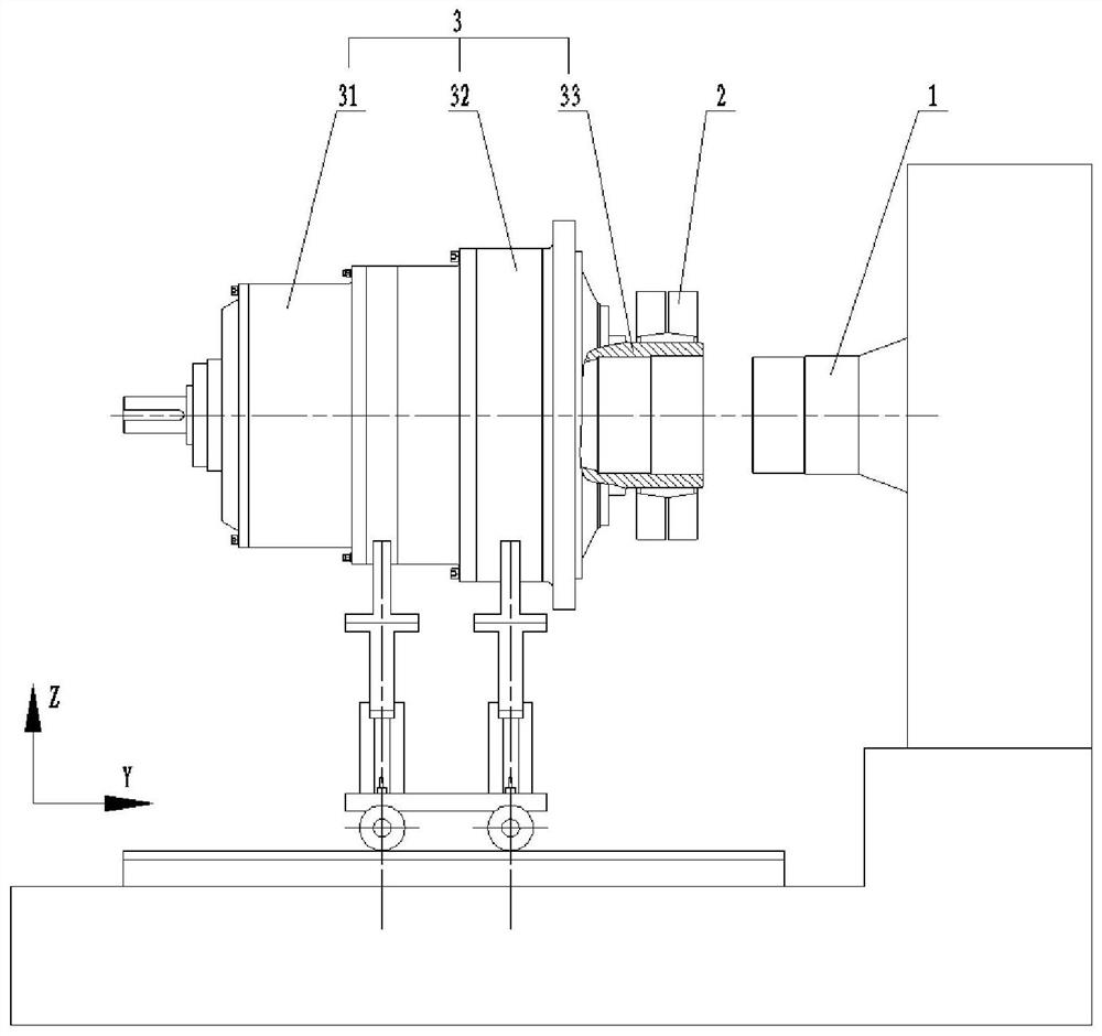
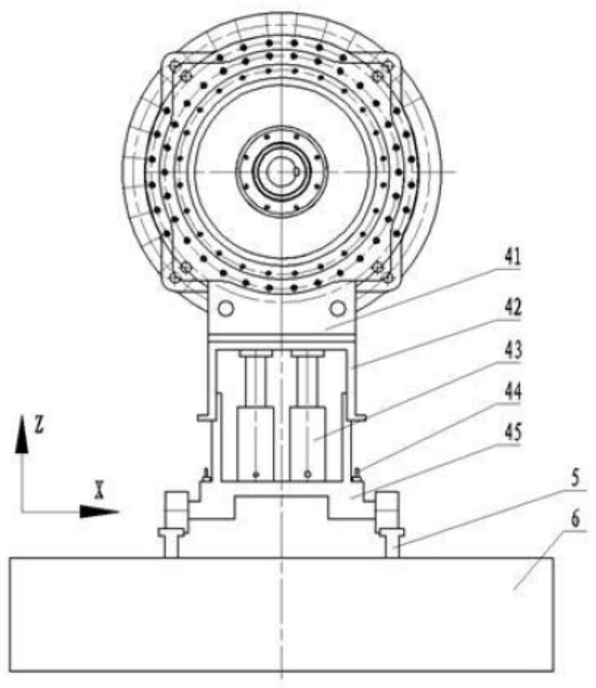
[0033] Example 1, see figure 1 , figure 2, an installation and disassembly device for a reducer for a rolling machine, comprising a rail trolley 45 that can only move along a horizontal track 5, and the horizontal rail 5 is longitudinally laid on the foundation 6 along the roller axis of the roller press; the rail trolley 45 is provided with two auxiliary support devices, and the two auxiliary support devices are distributed longitudinally along the roller shaft of the roller press, and the two auxiliary support devices respectively support the two parts of the reducer through a reducer support wallboard 41; the reducer The supporting part of the supporting wallboard 41 is an arc-shaped groove structure; the arc sizes of the two grooves match the dimensions of the inner ring gear 32 of the reducer and the outer circle of the box body 31 respectively, and the supporting wallboard 41 of the reducer can be raised and lowered And it can be arranged on the rail trolley 45 in a la...
Embodiment 2
[0039] Example 2, combined with figure 1 with figure 2 , a method for installing a speed reducer for a roller press, implemented based on the device of Example 1; comprising the following steps:
[0040] In the first step, the reducer 1 is hung on the reducer supporting wallboard 41 to form support for the two parts of the reducer through the reducer supporting wallboard 41;
[0041] The second step is to move the rail trolley 45 so that the hollow shaft 33 of the reducer is close to the roller shaft head of the roller press;
[0042] The third step is to support the wallboard 41 by lifting and moving the reducer laterally, so that the axis of the hollow shaft 33 of the reducer is aligned with the axis of the roller shaft of the roller press;
[0043] The fourth step is to connect the reducer 3 with the roller shaft 1 of the roller press through the locking of the locking disc 2 .
[0044] Among them, in the process of aligning the axis of the hollow shaft 33 of the reduce...
Embodiment 3
[0045] Example 3, combined with figure 1 with figure 2 , a method for disassembling a speed reducer for a roller press, implemented based on the device of Example 1; comprising the following steps:
[0046] In the first step, the rail trolley 45 provided with two auxiliary supporting devices is hoisted on the horizontal rail 5;
[0047] In the second step, the rail trolley 45 is moved so that the two auxiliary supporting devices are aligned with the two supporting parts of the speed reducer;
[0048] The third step is to adjust the height of the two auxiliary support devices and fine-tune the lateral position, so that the two auxiliary support devices respectively pass through the two supporting parts of the reducer to form a lift for the reducer;
PUM
 Abstract
Description
Claims
Application Information