3D printing supporting structure design method based on STL file

A support structure and 3D printing technology, applied in the field of 3D printing, can solve problems such as inability to achieve 100% detection, difficult removal of support structures, and troublesome post-processing stages, so as to save printing costs, save printing time, and be easy to remove Effect

Pending Publication Date: 2021-04-02
HANGZHOU DIANZI UNIV
View PDF5 Cites 13 Cited by
  • Summary
  • Abstract
  • Description
  • Claims
  • Application Information

AI Technical Summary

Problems solved by technology

Although this method can obtain a stable support structure, it is a waste of material, and after the model is formed, the support structure is also difficult to remove, which brings a lot of trouble to the post-processing stage
In addition, some models have sharp-edged areas to be supported, and the software will not do 100% detection

Method used


Image

  • 3D printing supporting structure design method based on STL file
  • 3D printing supporting structure design method based on STL file
  • 3D printing supporting structure design method based on STL file

Examples


Embodiment Construction

[0039] Embodiments of the present invention will be described in detail below in conjunction with the accompanying drawings.

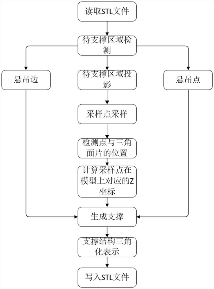
[0040] Such as Figure 1-9 As shown, a 3D printing support structure design method based on STL files includes the following steps:

[0041] S1. Use 3D modeling software to carry out 3D modeling of the model and export STL files. The 3D modeling software used can provide any 3D modeling software in STL format such as UG and Solidworks.

[0042] S2. Read the STL file by reading the STL file in Matlab, read the vertices and normal vector information of the triangular patches therein, and save all the vertex and normal vector information of the triangular patches into the rectangle variable.

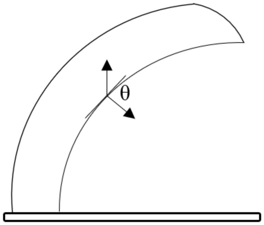
[0043] S3. Define the critical angle, and compare the angle between the external normal vector of the triangular surface and the positive direction of the Z axis with the critical angle, according to the formula: n·v=|n|·|v|cosθ, where the Z axis is positive The v...


PUM


Abstract

A 3D printing supporting structure design method based on an STL file comprises the following steps that 3D modeling software is used for conducting three-dimensional modeling on a model, the STL fileis exported, the STL file is read, triangular patch vertex and normal vector information in the STL file is read, a critical angle is defined, the read triangular patch information is integrated, a to-be-supported area is projected to a working plane to form a two-dimensional projection area to obtain a part needing to be supported, sampling point sampling is carried out to generate a supportingstructure, and all vertex coordinates and normal vector coordinates are written into an STL file. Compared with the prior art, the problems that a traditional supporting structure is excessive in useamount, materials are wasted, the supporting structure is difficult to remove, and a to-be-supported area of a sharp-angled model including a suspension edge, a suspension point and the like cannot bedetected are solved, by means of the 3D printing supporting structure design method based on the STL file, the calculation efficiency is improved on the premise of guaranteeing that the model is tender and is consolidated and stably printed, the printing cost is saved, and the supporting structure is easier to remove.

Description

technical field [0001] The invention belongs to the technical field of 3D printing, in particular to a 3D printing support structure design method based on STL files. Background technique [0002] Fused Deposition Manufacturing (Fused Deposition Modeling, FDM) technology is a common technology in 3D printing technology. It uses thermoplastic materials as printing raw materials to manufacture products by layer-by-layer printing. When printing, the printing material is heated and melted, and extruded into a filament directly under the nozzle. The nozzle moves along a certain path during the printing process. The filament material is extruded on the printing platform through the nozzle, and is rapidly cooled and solidified. With the emergence of fused deposition manufacturing technology, the design and optimization of support structures based on STL files has gradually become a hot topic. [0003] At present, most support structures rely on commercial slicing software, such as...

Claims


Application Information

Patent Timeline
Patent Type & Authority Applications(China)
IPC IPC(8): B29C64/118B29C64/386B29C64/40B33Y40/00B33Y50/00
CPCB29C64/118B29C64/386B29C64/40B33Y40/00B33Y50/00
Inventor 史廷春葛啸
Owner HANGZHOU DIANZI UNIV
Why Eureka
Try Eureka