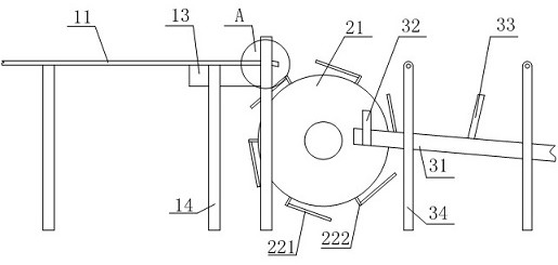
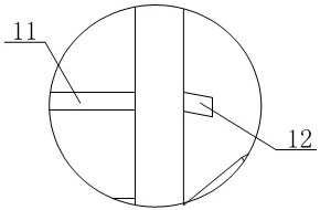
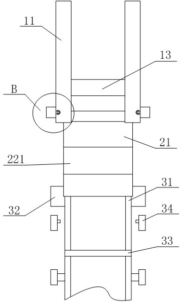
Turning conveying device for lamp circuit board machining

A technology of conveying device and direction changing device, which is applied in the direction of conveyors, conveyor objects, transportation and packaging, etc., and can solve problems such as low rotation speed, low conveying efficiency, and affecting conveying quality

Active Publication Date: 2021-04-02
山东三晶照明科技有限公司
View PDF6 Cites 2 Cited by
  • Summary
  • Abstract
  • Description
  • Claims
  • Application Information

AI Technical Summary

Problems solved by technology

[0002] During the processing of lamps and lanterns, they need to be assembled and installed. First, assemble the circuit board, and then use the circuit board to realize the connection and installation of the bulb and the circuit. When processing and transporting the circuit board, it is generally in the form of a conveyor belt. Application No. CN202022651646.X discloses a material changing direction conveying device, which can change the direction of material conveying, and realize vertical conveying after the horizontally conveyed material is rotated 90°, but when changing the direction of the material, due to the rotating wheel As well as the function of the limiter, when limiting the material conveyed horizontally, the rotation speed of the rotating wheel needs to be small, so as to ensure that the material falls onto the rotating wheel through the end of the first conveying device. During the rotation process of the rotating wheel The material in the middle slides into the limit piece to realize the direction-changing conveyance. This form of conveying efficiency is low, and it is easy for the material to fall due to weak contact with the limit piece, which affects the conveying quality.
[0003] In summary, there are obviously inconveniences and defects in the actual use of the existing technology, so it is necessary to improve

Method used


Image

  • Turning conveying device for lamp circuit board machining
  • Turning conveying device for lamp circuit board machining
  • Turning conveying device for lamp circuit board machining

Examples


Embodiment Construction

[0026] In order to make the objectives, technical solutions and advantages of the present invention clearer, the present invention will be described in further detail below in conjunction with the accompanying drawings and embodiments. It should be understood that the specific embodiments described here are only used to explain the present invention and are not intended to limit the invention.

[0027] It should be noted that, in the description of the present invention, terms such as "upper", "lower", "left", "right", "inner", "outer" and other indicated directions or positional relationships are based on the terms shown in the accompanying drawings. The direction or positional relationship shown is only for convenience of description, and does not indicate or imply that the device or element must have a specific orientation, be constructed and operated in a specific orientation, and thus should not be construed as limiting the present invention.

[0028] In addition, it shou...


PUM


Abstract

The invention is applicable to the technical field of material conveying, and provides a turning conveying device for lamp circuit board machining. The turning conveying device comprises a feeding device, a turning device and a collecting device, wherein the feeding device comprises a first conveying belt, an inclined block and a jacking device, the jacking device comprises a fixing shell, a rotating shaft and a jacking block, the jacking block comprises fixing rings and bulges, the turning device comprises a rotating wheel and a limiting piece, the collecting device comprises a material guiding plate, a telescopic piece and a limiting plate, a supporting plate is installed on the side face of the material guiding plate, a limiting block is installed at the upper end of the inner side of the supporting plate, the bottom of the limiting block is arc, a limiting column is arranged on one side of the extending section, a torsion spring is installed between the limiting block and the supporting plate, one side of the material guiding plate is provided with a moving space for containing the limiting plate, and elastic pieces are installed between the two sides of the end of the limitingplate and the moving space. According to the turning conveying device, the direction-changing conveying of materials can be effectively realized, and the working efficiency and the direction-changingconveying stability are improved.

Description

technical field [0001] The invention relates to the technical field of material direction-changing conveying, in particular to a direction-changing conveying device for lamp circuit board processing. Background technique [0002] During the processing of lamps and lanterns, they need to be assembled and installed. First, assemble the circuit board, and then use the circuit board to realize the connection and installation of the bulb and the circuit. When processing and transporting the circuit board, it is generally in the form of a conveyor belt. Application No. CN202022651646.X discloses a material changing direction conveying device, which can change the direction of material conveying, and realize vertical conveying after the horizontally conveyed material is rotated 90°, but when changing the direction of the material, due to the rotating wheel As well as the function of the limiter, when limiting the material conveyed horizontally, the rotation speed of the rotating wh...

Claims


Application Information

Patent Timeline
Patent Type & Authority Applications(China)
IPC IPC(8): B65G47/24B65G23/22B65G15/30B65G49/06B65B35/44B65B35/56B65B13/18
CPCB65B13/18B65B35/44B65B35/56B65G15/30B65G23/22B65G47/24B65G49/06
Inventor 李福忠
Owner 山东三晶照明科技有限公司
Why Eureka
Try Eureka