Oil system and method of controlling oil system

A technology of oil system and flow control, applied in the field of oil system

Active Publication Date: 2022-08-05
VOLVO LASTVAGNAR AB
View PDF5 Cites 0 Cited by
  • Summary
  • Abstract
  • Description
  • Claims
  • Application Information

AI Technical Summary

Problems solved by technology

Sizing the oil system for the maximum possible pressure demand can often result in unnecessarily high oil pump duty

Method used


Image

  • Oil system and method of controlling oil system
  • Oil system and method of controlling oil system
  • Oil system and method of controlling oil system

Examples


Embodiment Construction

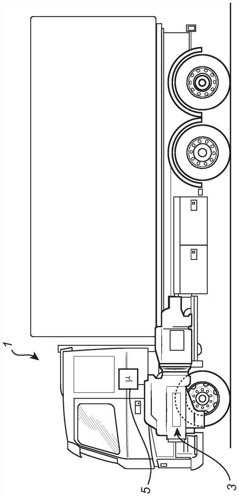
[0030] figure 1 A vehicle according to an exemplary embodiment of the invention is shown schematically, here in the form of a truck 1 and comprising an ICE device 3 . The ICE device 3 includes a control unit 5 for controlling the operation of the ICE device 3 . The ICE unit 3 includes an oil system 7 for lubricating and cooling the ICE unit 3 (at figure 1 not visible in).

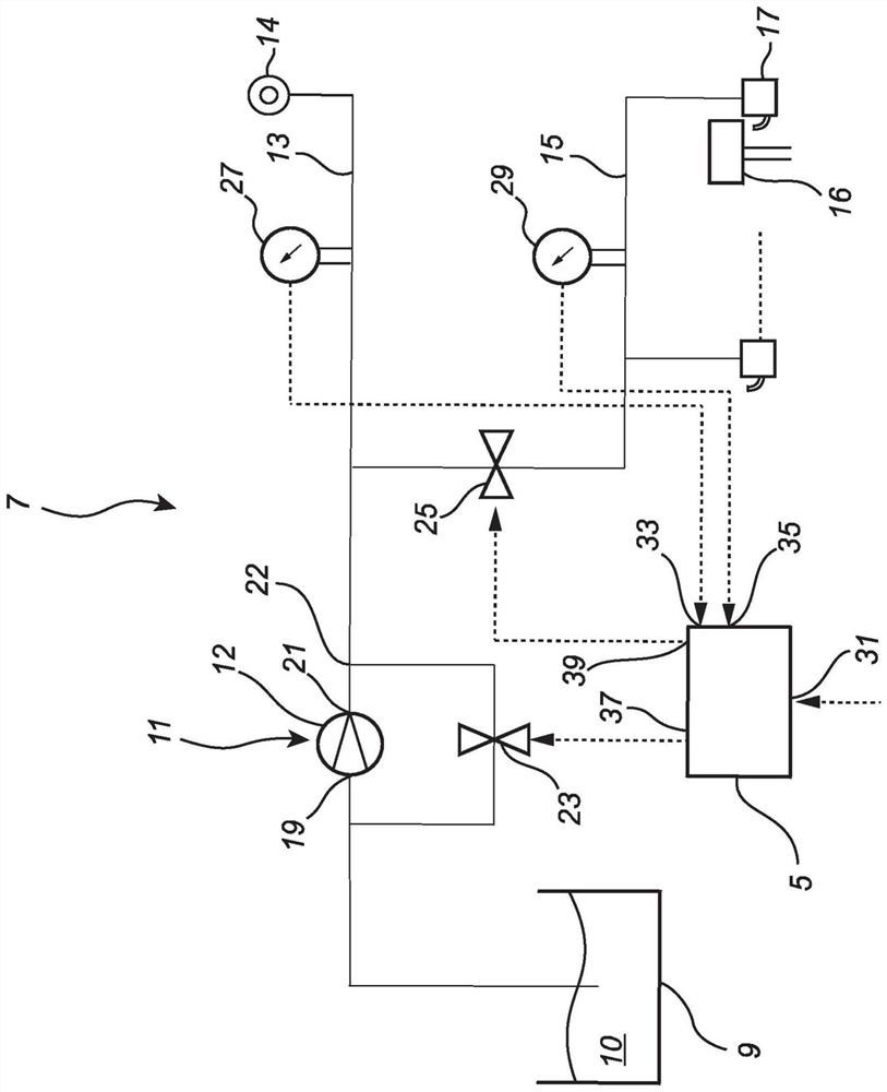
[0031] figure 2 is a simplified schematic diagram of an oil system according to an example embodiment of the present invention. For example, various components that are not core to the present invention have been omitted. Such components may include, for example, oil filters and oil heaters, among others. However, such and other oil system components are well known to those of ordinary skill in the art.

[0032] refer to figure 2 , the oil system 7 comprises an oil reservoir 9 containing oil 10, a controllable pump device 11 fluidly connected to the oil reservoir 9, a first oil passage 13 fluidly con...


PUM


Abstract

The invention relates to an oil system (7), comprising: a pump device (11); a first oil passage (13) for supplying oil to a first engine part (14); a second oil passage (15) for supplying oil to the second engine part (16); a second oil passage flow control device (25) for controlling the flow of oil from the pump device (11) to the second oil passage (15); a control circuit (5); A pressure sensor (27) for sensing the oil pressure in the first oil passage (13); and a second pressure sensor (29) for sensing the oil pressure in the second oil passage (15). The oil system (7) can be controlled between the following states: a first state in which the control circuit (5) controls the second oil passage flow control device (25) to an open state, and through controlling the pump means (11) to control the oil pressure in the second oil gallery (15); and a second state in which the control circuit (5) controls the first oil by controlling the pump means (11) The oil pressure in the passage (13) is controlled, and the oil pressure in the second oil passage (15) is controlled by controlling the second oil passage flow control device (25).

Description

technical field [0001] The present invention relates to an oil system, a method of controlling the oil system, and an internal combustion engine device. [0002] The present invention can be applied to heavy vehicles such as trucks, buses and construction equipment. Although the invention will be described with respect to trucks, the invention is not limited to this particular vehicle, but may also be used in other vehicles such as buses or construction machinery such as wheel loaders or excavators, etc. Background technique [0003] Internal combustion engines (ICEs) have oil systems for lubricating and / or cooling various components of the ICE. The oil system usually has an oil pump for pumping oil from the oil pan to different so-called oil passages. From each oil passage, oil is supplied to different components of the ICE. A diesel engine, for example, may have a main gallery for supplying oil to crankshaft bearings, etc. and a piston cooling jet (PCJ) gallery for supp...

Claims


Application Information

Patent Timeline
Patent Type & Authority Patents(China)
IPC IPC(8): F01M1/16F01M1/20F01M1/08
CPCF01M1/08F01M1/16F01M1/20F16N2250/04F16N2270/60F01M1/02F01M5/002F01M11/0004F01M11/02F01M2250/60
Inventor 法比安·黑勒曼
Owner VOLVO LASTVAGNAR AB
Why Eureka
Try Eureka