
Rapid cooling device for automobile injection molding part

A rapid cooling and injection molded parts technology, applied in the field of automobile manufacturing, can solve the problems of low production efficiency, easy deformation, and deformation of injection molded parts, and achieve the effects of reducing time, improving production efficiency, and reducing the probability of deformation

Inactive Publication Date: 2021-04-06
十堰市雨佳工贸有限公司
View PDF1 Cites 0 Cited by
  • Summary
  • Abstract
  • Description
  • Claims
  • Application Information

AI Technical Summary

Problems solved by technology

[0006] In order to solve the above technical problems, the present invention provides a rapid cooling device for injection molded parts of automobiles to solve the problem that the current common cooling devices for injection molded parts proposed in the above background technology mainly set water cooling pipes in the extrusion core, and generally do not set injection molded parts. The secondary cooling structure after forming and falling, the injection molded parts have not been completely cooled after falling off, and the high temperature injection molded parts are easy to deform after being piled up and extruded. The temperature cooling is not fast enough during the process, resulting in low production efficiency of injection molded parts

Method used


Image

  • Rapid cooling device for automobile injection molding part
  • Rapid cooling device for automobile injection molding part
  • Rapid cooling device for automobile injection molding part

Examples


Embodiment

[0027] as attached figure 1 to attach Figure 5 Shown:

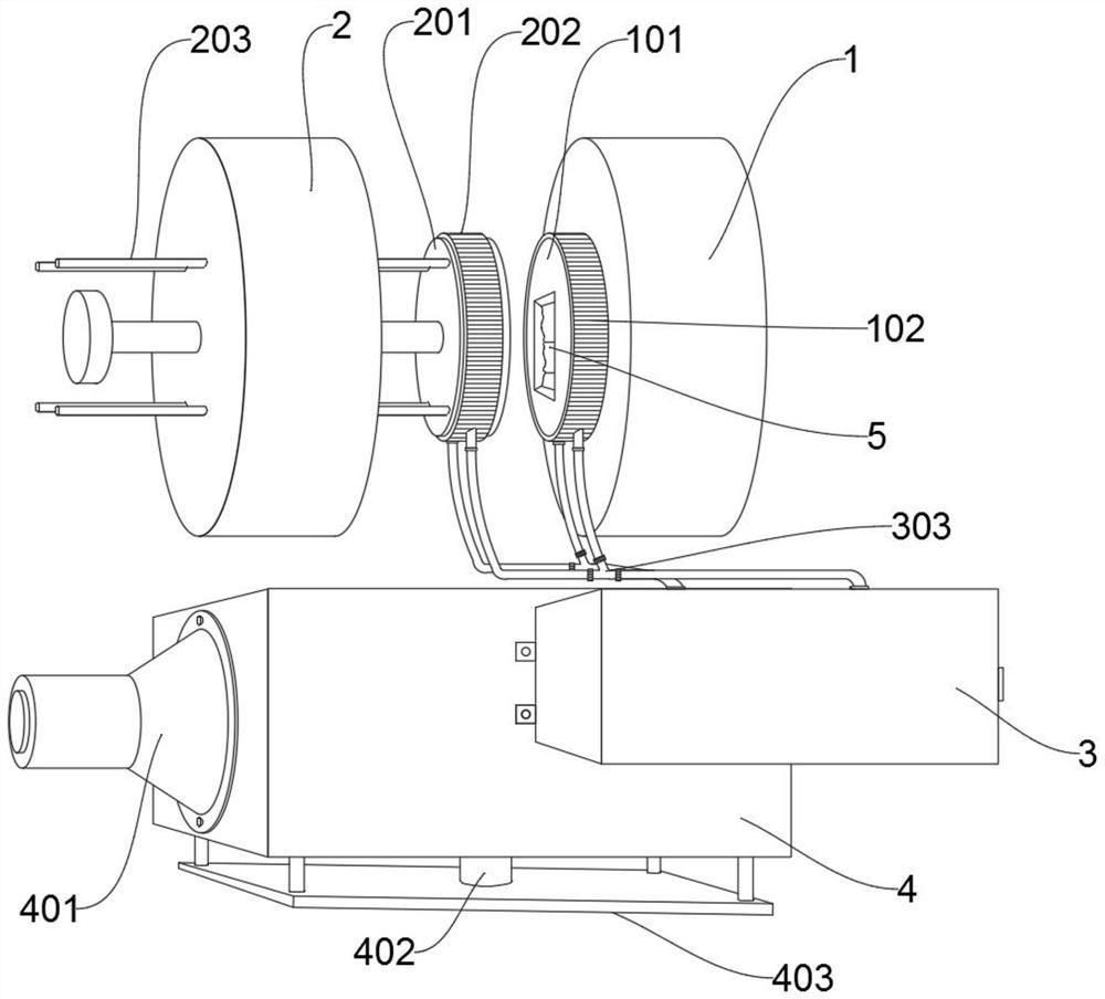
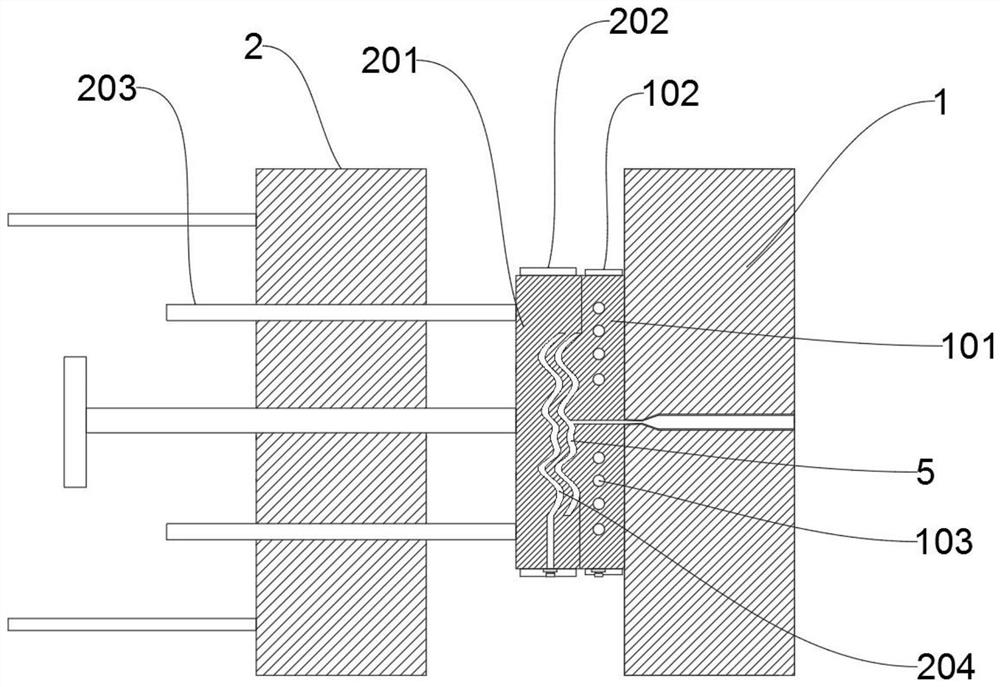
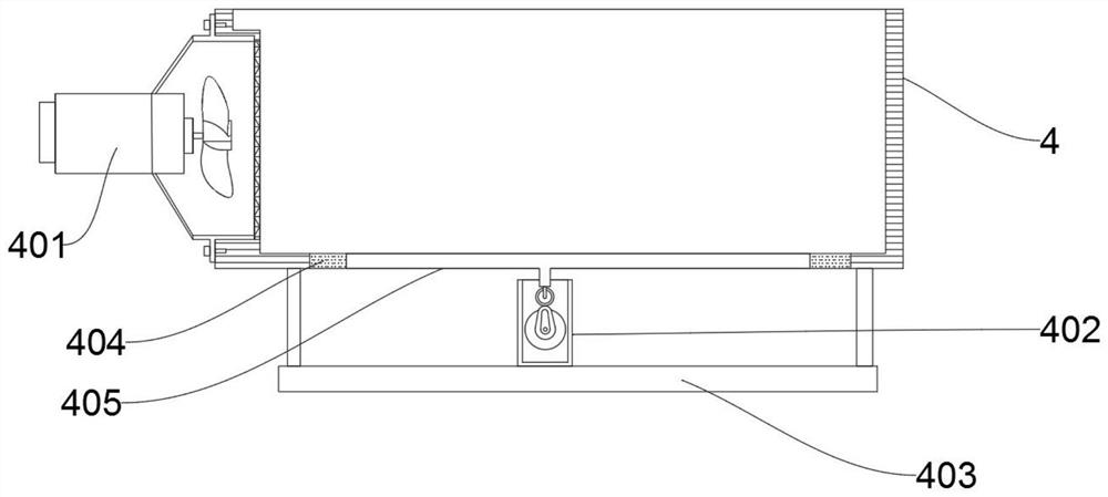
[0028] The present invention provides a rapid cooling device for injection molded parts of automobiles, which includes a feed block 1 and a retaining block 2; the inside of the feed block 1 is provided with a feed gate through casting, and the side of the feed block 1 is fixedly connected with a fixed mold core 101; The curved side of the fixed mold core 101 is provided with heat sink A102 through screw connection; the interior of the fixed mold core 101 is provided with a condensation pipe 103; Extrusion core 201 is connected; the curved side of extrusion core 201 is provided with heat sink B202 through screw connection; cooling bucket 4 is arranged under extrusion core 201; base 403 is fixedly connected to the bottom of cooling bucket 4, and the top of base 403 The surface is fixedly connected with an electric cam machine 402; the side of the cooling bucket 4 is provided with a circulating pump 3 through screw connec...


PUM


Abstract

The invention provides a rapid cooling device for an automobile injection molding part. The rapid cooling device comprises a feeding block and a retention block. A feeding sprue is formed in the feeding block through casting, and a fixed mold core is fixedly connected to the side face of the feeding block. The curved side surface of the fixed mold core is provided with cooling fins A through threaded connection. A condensation pipeline is arranged in the fixed mold core. Four sets of push rods are arranged in the retention block through molded surface connection. The side surfaces of the push rods are connected with an extrusion mold core through a flange. Cooling fins B are arranged on the curved side surface of the extrusion mold core through threaded connection. A cooling hopper is arranged below the extrusion mold core. The bottom of the cooling hopper is fixedly connected with a base, and the top surface of the base is fixedly connected with an electric cam machine. A circulating pump is arranged on the side surface of the cooling hopper through threaded connection. Through the arrangement of an air blower and a moving plate, the moving plate can be driven to vertically move through the electric cam machine, the injection molding part can be secondarily cooled through operation of the air blower, and the cooling time of the injection molding part is shortened.

Description

technical field [0001] The invention belongs to the technical field of automobile manufacturing, and more specifically relates to a rapid cooling device for injection molded parts of automobiles. Background technique [0002] Injection molding, also known as injection molding, is a molding method of injection and molding. At a certain temperature, the completely molten plastic material is stirred by a screw, injected into the mold cavity with high pressure, and cooled and solidified to obtain a molded product. This method is suitable for mass production of complex-shaped parts, and is one of the important processing methods. Injection molding is suitable for mass production and complex-shaped products and other molding processing fields. [0003] After searching, for example, the patent No. CN210705885U discloses a cooling device for injection molded parts, including a solid component and a water cooling component. The solid component includes a bracket, a supporting base, ...

Claims


Application Information

Patent Timeline
IPC IPC(8): B29C45/73B29C45/72
CPCB29C45/7207B29C45/7312
Inventor 徐刚左刚杜顺良
Owner 十堰市雨佳工贸有限公司
Learn More