Point switch control device

A control device and switch machine technology, applied in the interlocking devices between turnouts and signals, transportation and packaging, railway car body parts, etc., can solve problems such as difficult maintenance, large space occupied by control circuits, and complicated construction, and achieve The effect of simplifying the control method

Active Publication Date: 2021-04-06
BEIJING HOLLYSYS
View PDF10 Cites 5 Cited by
  • Summary
  • Abstract
  • Description
  • Claims
  • Application Information

AI Technical Summary

Problems solved by technology

[0006] 1. Large size: a single gravity relay is relatively large in size, and at least 5 relays are needed to realize a turnout control circuit, and the entire control circuit takes up a lot of space;
[0007] 2. Complex construction: Relays, buttons, fuses, buttons and other devices used in the turnout control circuit must be wired. The number of wiring is large, the construction is difficult, and it is easy to make mistakes. It is difficult to check and check;
[0008] 3. No monitoring: There is no monitoring circuit in the turnout control circuit, and the operating parameters during the turnout control process cannot be detected, and status analysis and fault prediction cannot be performed; if monitoring is required, a separate monitoring system needs to be added, which is complex and costly ;
[0009] 4. Difficulty in maintenance: There are many devices in the turnout control circuit and the wiring is complicated. Once a fault occurs, it is difficult to quickly locate the cause of the fault, which brings great pressure to system maintenance.

Method used


Image

  • Point switch control device
  • Point switch control device
  • Point switch control device

Examples


Embodiment Construction

[0034] In order to make the purpose, technical solutions and advantages of the embodiments of the present application clearer, the embodiments of the embodiments of the present application will be described in detail below with reference to the accompanying drawings. It should be noted that, in the case of no conflict, the embodiments in the embodiments of the present application and the features in the embodiments can be combined arbitrarily with each other.

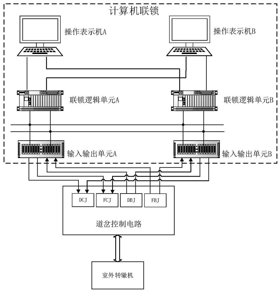
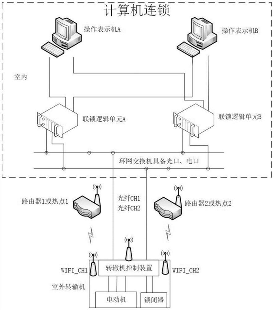
[0035] The embodiment of the present application provides a switch machine control device, which is arranged inside the switch machine, and includes a power supply module, a strong current control module and a trackside control module, wherein:

[0036] The power module supplies power to the device;

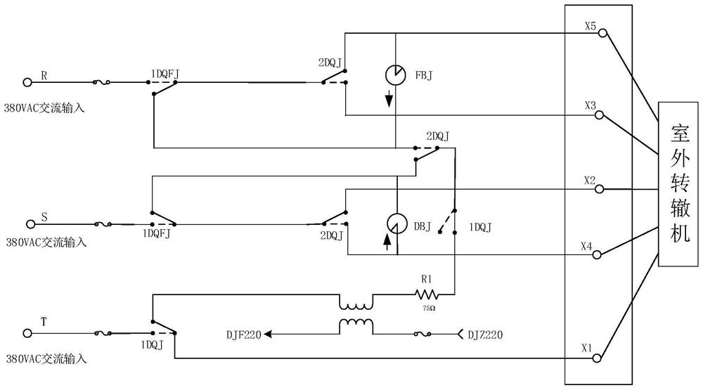
[0037] The heavy current control module includes a turnout control circuit, a power supply control circuit, a first switch control circuit and a second switch control circuit, wherein:

[0038] The switch control circuit ...


PUM


Abstract

The embodiment of the invention discloses a point switch control device which is arranged in a point switch and comprises a power module; a strong current control module which comprises a turnout control loop, a power switch control circuit, a first switch control circuit and a second switch control circuit, and the turnout control loop is connected with a motor of the point switch through three control circuits U, V and W and comprises three power switches, three first switches and four second switches; a power supply control circuit which is used for controlling the three power supply switches to be switched on or off; a first switch control circuit which is used for controlling the three first switches to be switched on or off; a second switch control circuit which is used for controlling one of the four second switches to be closed; and a trackside control module which is used for receiving the operation instruction sent by the computer interlocking system, controlling the load switch machine through the turnout control loop, and reporting the state of the switch machine and the state information of the turnout control loop to the computer interlocking system.

Description

technical field [0001] The embodiment of the present application relates to the field of track control, in particular to a switch machine control device. Background technique [0002] In the signal system, the interlock system is used for the control of station signals. Computer interlocking equipment has been popularized and applied for nearly 20 years, and a relatively mature product structure and technical conditions have been formed. The control logic and external structure of the current computer interlocking equipment are still inherited from the 6502 electrical centralized interlocking system, and its external equipment still uses the gravity type safety relay as the medium to carry out safety input and output control, by controlling the gravity type safety relay coil to pick up or fall Manipulate the action of outdoor equipment, and obtain the status of outdoor equipment through the state of relay contacts. [0003] Such as figure 1 As shown, it is a five-wire sin...

Claims


Application Information

Patent Timeline
Patent Type & Authority Applications(China)
IPC IPC(8): B61L5/06B61L19/14
CPCB61L5/06B61L19/14
Inventor 何鹏徐刚张明军廖亮崔转铃张龙李海平王鑫
Owner BEIJING HOLLYSYS
Why Eureka
Try Eureka