Eureka AIR delivers breakthrough ideas for toughest innovation challenges, trusted by R&D personnel around the world.

Spiral spark extinguishing multi-cavity silencer

A muffler and Mars technology, which is applied in the direction of mufflers, machines/engines, engine components, etc., can solve the problems of large flow resistance and exhaust back pressure of exhaust pipes, large amount of diesel oil used, narrow muffler frequency band, etc.

Pending Publication Date: 2021-04-06
JIANGSU YEAN IND ENVIRONMENTAL PROTECTION EQUIP TECH
View PDF0 Cites 0 Cited by
  • Summary
  • Abstract
  • Description
  • Claims
  • Application Information

AI Technical Summary

Problems solved by technology

At present, the exhaust muffler for marine internal combustion engines is mainly an expansion muffler used to eliminate middle and low frequency noise. It often has a narrow muffler frequency band, which makes it difficult to cover the noise frequency band with higher sound waves, or easily forms a large flow resistance and noise in the exhaust pipeline. Exhaust back pressure, large internal combustion engine power loss
[0004] Diesel engines use a lot of diesel. Carbon particles are produced when the diesel is not fully burned in the combustion chamber. When there are flammable and combustible materials, it is easy to cause a fire alarm due to combustion, and even cause an explosion of the surrounding combustible gas, resulting in a catastrophic accident. Therefore, how to realize a muffler with high-efficiency noise reduction and spark extinguishing function has become an urgent problem for those skilled in the art. main technical issues

Method used


Image

  • Spiral spark extinguishing multi-cavity silencer
  • Spiral spark extinguishing multi-cavity silencer

Examples


Embodiment Construction

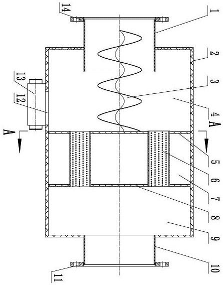
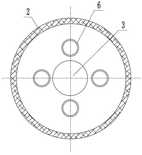
[0019] Such as figure 1 , figure 2 The spiral Mars extinguishing multi-cavity muffler shown in the figure has a cylindrical structure of the muffler cylinder 2. The muffler cylinder 2 adopts a double-layer structure, and the double wall of the cylinder wall is filled with sound-absorbing materials. The sound-absorbing material is rock cotton or fiberglass. The inner cylinder wall of the muffler cylinder 2 is a perforated plate, and the perforated plate is evenly distributed with a number of perforations, the perforation rate is 30%, and the perforation aperture (perforation diameter) is 5mm. There is a glass fiber cloth layer made of glass fiber cloth. An air intake pipe 1 is arranged at one end of the muffler cylinder 2, and an air intake pipe flange 14 is installed on the extended end of the air intake pipe 1; There is an outlet pipe flange 11. Both the air inlet pipe 1 and the air outlet pipe 10 are circular bobbins, and the air inlet pipe 1 and the air outlet pipe 10 ...


PUM

PropertyMeasurementUnit
Perforation apertureaaaaaaaaaa

Abstract

The invention discloses a spiral spark extinguishing multi-cavity silencer. An air inlet pipe is arranged at one end of a silencer cylinder body, an air outlet pipe is arranged at the other end of the silencer cylinder body, a cylinder wall of the silencer cylinder body is of a double-layer structure, a cylinder wall cavity is filled with sound absorption materials, and an inner cylinder wall of the silencer cylinder body is a perforated plate. A front partition plate and a rear partition plate are fixedly arranged in a cylinder cavity of the silencer cylinder body at intervals and divide the cylinder cavity of the silencer cylinder body into a front expansion cavity, a middle expansion cavity and a rear expansion cavity. At least two perforated pipes are supported on the front partition plate and the rear partition plate, one end of each perforated pipe leads to the front expansion cavity, and the other end of each perforated pipe leads to the rear expansion cavity; a spiral flow deflector is fixedly mounted on the front partition plate and extends into a pipe of the air inlet pipe; and an ash collecting opening is formed in the silencer cylinder body and leads to the ash collecting hopper from the interior of the cylinder cavity of the silencer cylinder body. The multi-cavity silencer not only is wide in silencing frequency band and small in exhaust resistance, but also can quickly extinguish sparks.

Description

technical field [0001] The invention relates to an exhaust muffler for a diesel engine, in particular to a muffler capable of reducing noise at the exhaust nozzle of a marine diesel engine and extinguishing sparks. Background technique [0002] The acoustic performance of the muffler requires a sufficiently high muffler in the required muffler frequency range, the aerodynamic performance requires the muffler to have less resistance to the airflow, and the increased pressure loss after the muffler is installed must be controlled within the actual allowable range. If the aerodynamic performance of the muffler is poor and the resistance of the exhaust system is large, the fuel consumption of the internal combustion engine will be increased and the output power will be reduced. The existing muffler is generally of a single structure, which often cannot meet the respective requirements of low frequency and high frequency. It is difficult to unify to high noise reduction quantity ...

Claims


Application Information

Patent Timeline
IPC IPC(8): F01N1/10F01N3/037F01N3/06
CPCF01N1/082F01N1/089F01N1/10F01N3/037F01N3/06
Inventor 梅冬生季振林肖友洪严桂芳
Owner JIANGSU YEAN IND ENVIRONMENTAL PROTECTION EQUIP TECH
Why Eureka
Eureka Blog
Learn More