Hardware current sharing device and working method thereof

A working method and hardware technology, which can be used in measuring devices, measuring flow/mass flow, liquid/fluid solids measurement, etc., and can solve the problems of low sensitivity to load mutation and low accuracy of current sharing.

Pending Publication Date: 2021-04-06
SUZHOU LANGCHAO INTELLIGENT TECH CO LTD
View PDF6 Cites 1 Cited by
  • Summary
  • Abstract
  • Description
  • Claims
  • Application Information

AI Technical Summary

Problems solved by technology

[0005] The present application provides a hardware current sharing device and its working method to solve the problems that t

Method used


Image

  • Hardware current sharing device and working method thereof
  • Hardware current sharing device and working method thereof
  • Hardware current sharing device and working method thereof

Examples


Embodiment 1

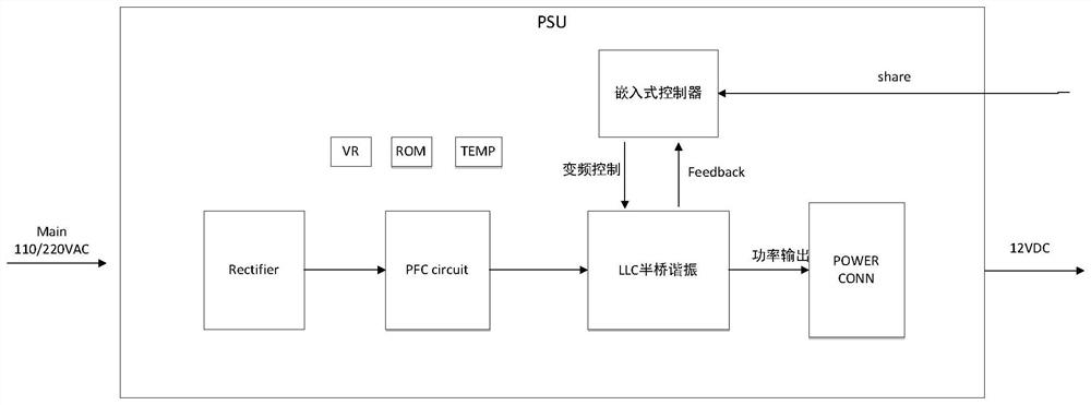
[0044] The hardware current sharing device in this application is mainly used in multi-node servers, where each node is matched with a PSU, multiple PSUs are connected in parallel, and each PSU is equipped with a hardware current sharing IC, referred to as a current sharing IC .

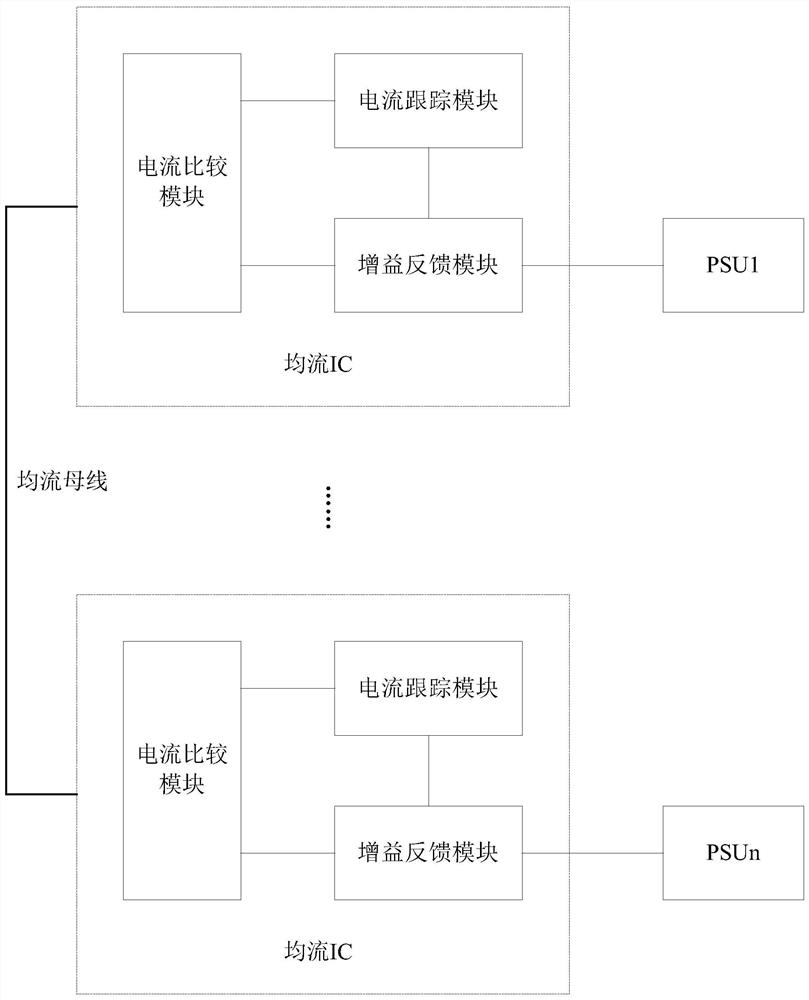
[0045] The hardware current sharing device in this embodiment can be found in figure 2 , figure 2 It is a schematic structural diagram of a hardware current sharing device provided in the embodiment of the present application. Depend on figure 2 It can be seen that the hardware current sharing device in this embodiment mainly includes: multiple current sharing ICs, at least two current sharing ICs, and the multiple current sharing ICs are connected through a current sharing bus. Any current sharing IC includes: current comparison module, current tracking module and gain feedback module. Hardware current sharing IC is a high performance, low cost load sharing controller. Among them, the curren...

Embodiment 2

[0053] exist Figure 2-Figure 4 On the basis of the illustrated embodiment see Figure 5 , Figure 5 It is a schematic flowchart of a working method of a hardware current sharing device provided in the embodiment of the present application. Depend on Figure 5 It can be seen that the working method of the hardware current sharing device in this embodiment mainly includes the following processes:

[0054] S1: Obtain the current output current of the PSU.

[0055] Obtain the current output current of the PSU through the current detection pin of the current sharing IC.

[0056] S2: Obtain the output currents of other PSUs in the multi-node server.

[0057] Obtain the output current of other PSUs through the current sharing bus. Steps S1 and S2 can also be executed simultaneously.

[0058] S3: Compare multiple output currents.

[0059] The multiple output currents in this embodiment include: the output current of the current PSU and the output currents of other PSUs, the P...


PUM


Abstract

The invention discloses a hardware current sharing device and a working method thereof, the device comprises a plurality of current sharing ICs, the plurality of current sharing ICs is connected through a current sharing bus, and any current sharing IC comprises a current comparison module, a current tracking module and a gain feedback module. The method comprises the steps of obtaining an output current of a current PSU; obtaining output currents of other PSUs in the multi-node server; comparing the plurality of output currents, with the plurality of output currents including the output current of the current PSU and the output currents of other PSUs, defining the PSU with the maximum current as a master module, and defining the other PSUs as slave modules; controlling the slave modules to adjust the output current according to the difference between the output current of the master module and the output currents of the slave modules; acquiring feedback current in a transconductance mode according to the comparison result of the multiple output currents and the output currents adjusted by the slave modules; and outputting the feedback current to LLC half-bridge resonance in the PSUs. According to the invention, the PSU current sharing sensitivity and current sharing precision can be effectively improved, and the stability of a server system is improved.

Description

technical field [0001] The present application relates to the technical field of multi-node server hardware current sharing, in particular to a hardware current sharing device and a working method thereof. Background technique [0002] In a multi-node server, since there are many server nodes, and each node has more SSD (Solid State Drives, solid-state drive) hard disks, NVME (NVME (Non-Volatile Memory express, non-volatile memory host controller interface specification ) hard disk and various network cards, plus the power consumption of the CPU, the power consumption of the entire single multi-node server is high, which requires the introduction of multiple PSUs (Power Supply Units, power supply units), or at least 2 PSUs for Power supply for the entire single multi-node server. Taking two PSUs as an example, when the two PSUs are in place at the same time, the output power of the two PSUs cannot be consistent due to factors such as power cables, power interfaces, and PDB b...

Claims


Application Information

Patent Timeline
IPC IPC(8): G06F1/26
CPCG06F1/263
Inventor 张晓鹏
Owner SUZHOU LANGCHAO INTELLIGENT TECH CO LTD
Why Eureka
Try Eureka