Compact low-coupling extensible MIMO antenna based on orthogonal mode
An orthogonal mode and compact technology, which is applied in the field of compact low-coupling scalable MIMO antennas, can solve the problems of complex antenna structures, inability to popularize MIMO systems, and the inability to effectively reduce the overall size of antennas to achieve low-coupling effects
- Summary
- Abstract
- Description
- Claims
- Application Information
AI Technical Summary
Problems solved by technology
Method used
Image
Examples
Embodiment 1
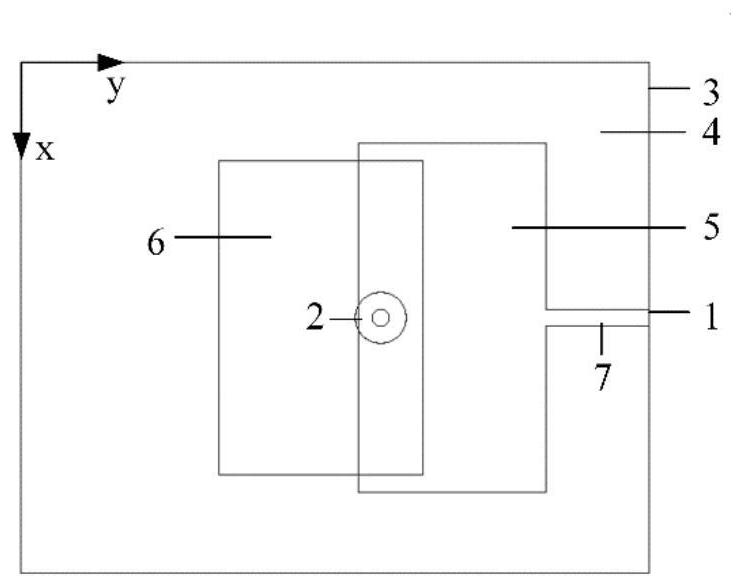
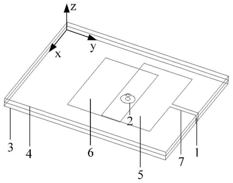
[0055] As shown in Figure 1, the compact low-coupling scalable MIMO antenna based on orthogonal mode includes microstrip line feed port 1, coaxial line feed port 2, ground metal plate 3, metal microstrip feed line 7, double-layer A dielectric plate and a rectangular radiating metal patch 9 , the rectangular radiating metal patch 9 includes a first rectangular radiating metal patch 5 and a second rectangular radiating metal patch 6 . The coaxial line feed port 2 is located at the zero point of the electric field distribution generated by the microstrip line feed port 1, the double-layer dielectric plate is arranged above the grounded metal plate 3, and the first rectangular radiation metal patch 5 is connected through the metal microstrip feed line 7 To the feed port 1 of the microstrip line, the second rectangular radiating metal patch 6 is connected to the feed port 2 of the coaxial line through a coaxial probe.
[0056] The upper and lower dielectric boards of the double-lay...
Embodiment 2
[0064] This embodiment is improved on the basis of Embodiment 1, and no double-layer dielectric board and two radiating metal patches are needed. Referring to FIG. The patch 9 is one piece, and a gap ring 8 is etched with the center of the rectangular radiating metal patch 9 as the center. The grounding metal plate 3, the single-layer dielectric plate and the rectangular radiating metal patch 9 are placed in parallel in the vertical direction, and the grounding metal The midpoints or centers of the board 3 , the single-layer dielectric board, the rectangular radiating metal patch 9 and the gap ring 8 are all located on a straight line parallel to the z-axis. Wherein the metal microstrip feeder 7 is an irregular shape, and the rectangular radiation metal patch 9 covers the top surface of the single-layer dielectric board, and is connected to the coaxial feeder port 2 by the metal microstrip feeder 7, and the coaxial probe is placed In the single-layer dielectric board, the rect...
Embodiment 3
[0070] The compact low-coupling scalable MIMO antenna system based on the orthogonal mode in this embodiment includes several antenna units, as shown in FIG. Rectangular radiating metal patch 9, single-layer dielectric board, and grounding metal board 3.
[0071] The antenna grounding metal plate 3 adopts a grounding rectangular metal patch, the size of the metal grounding plate 3 is the same as that of the bottom surface of the dielectric plate 4 , and the rectangular radiating metal patch 9 covers the top surface of the dielectric plate 4 .
[0072] The material of the dielectric plate 4 in this embodiment is epoxy resin plate FR4 with a dielectric constant of 4.4, placed on the xoy surface, as shown in Figure 12, the size of the microstrip unit forming this embodiment is 197.1mm×197.1mm ×2.5mm, the size of the upper patch is 187.7mm×187.7mm, the overall size of the antenna unit is 0.49λ 0 ×0.49λ 0 ×0.006λ 0 , where λ 0 is the free-space wavelength at a center frequency ...
PUM
| Property | Measurement | Unit |
|---|---|---|
| Impedance bandwidth | aaaaa | aaaaa |
Abstract
Description
Claims
Application Information
 - R&D
- Intellectual Property
- Life Sciences
- Materials
- Tech Scout
- Unparalleled Data Quality
- Higher Quality Content
- 60% Fewer Hallucinations
Browse by: Latest US Patents, China's latest patents, Technical Efficacy Thesaurus, Application Domain, Technology Topic, Popular Technical Reports.
© 2025 PatSnap. All rights reserved.Legal|Privacy policy|Modern Slavery Act Transparency Statement|Sitemap|About US| Contact US: help@patsnap.com


