Punching equipment for metal chain wheel manufacturing

A technology of punching equipment and cranksets, applied in metal processing equipment, drilling/drilling equipment, manufacturing tools, etc., can solve the problems of labor-intensive, cumbersome operation process, low work efficiency, etc. Simple, labor-saving effect

Active Publication Date: 2021-04-09
佛山市凯泽金属制品有限公司
View PDF8 Cites 1 Cited by
  • Summary
  • Abstract
  • Description
  • Claims
  • Application Information

AI Technical Summary

Problems solved by technology

[0006] In order to overcome the disadvantages that the operation process of the above method is cumbersome, the operation is relatively labor-intensive, and only one hole can be punched at a time in the process of punching, and the work efficiency is low, the technical problem to be solved by the invention is to provide a Drilling equipment for manufacturing metal cranks that saves manpower during operation and improves work efficiency

Method used


Image

  • Punching equipment for metal chain wheel manufacturing
  • Punching equipment for metal chain wheel manufacturing
  • Punching equipment for metal chain wheel manufacturing

Examples


Embodiment 1

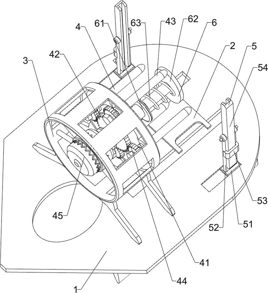
[0026] A kind of drilling equipment for the manufacture of metal chainrings, such as Figure 1-2 As shown, it includes a chassis 1, a backing plate 2 and an installation frame 3, the backing plate 2 is connected to the top front side of the chassis 1, the installation frame 3 is connected to the top rear side of the chassis 1, and a driving device 4, a guiding device 5 and a buffer are also included. The device 6 is provided with a drive device 4 inside the installation frame 3 , a buffer device 6 is provided on the drive device 4 , and a guide device 5 is provided on the chassis 1 .

[0027] The driving device 4 includes a connecting plate 41, a middle gear 42, a drill bit 43, a side gear 44 and a motor 45. The front side of the installation frame 3 is connected with a connecting plate 41, and the middle part of the connecting plate 41 is rotatably connected with a middle gear 42, and the connecting plate 41 Four drill bits 43 are connected with evenly spaced rotation along t...

Embodiment 2

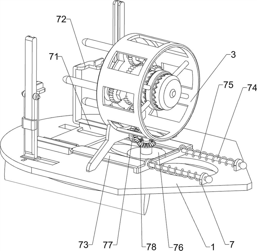
[0032] On the basis of Example 1, such as image 3 As shown, transmission device 7 is also included, transmission device 7 includes slide frame 71, L-shaped guide plate 72, U-shaped plate 73, guide rod 74, connecting spring 75, cam 76, transmission gear 77 and bevel gear 78, chassis 1 The left and right sides of the top are connected with a slide frame 71, and the slide frame 71 is slidably connected with an L-shaped guide plate 72, and a U-shaped plate 73 is connected between the L-shaped guide plates 72 on both sides, and the left and right sides of the U-shaped plate 73 rear sides are A guide rod 74 is connected, and the guide rod 74 is slidably matched with the chassis 1. A connecting spring 75 is connected between the guide rod 74 and the chassis 1. A cam 76 is connected to the middle part of the chassis 1 in a rotatable manner. The cam 76 cooperates with the U-shaped plate 73, and the chassis 1 The top rotation type is connected with transmission gear 77, and transmissio...

Embodiment 3

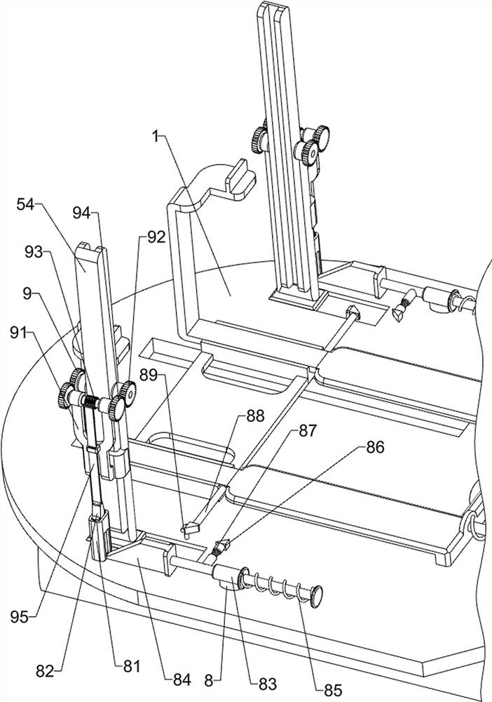
[0035] On the basis of Example 2, such as Figure 4As shown, it also includes an interlocking device 8, and the interlocking device 8 includes a ferrule 81, a lifting block 82, a connecting sleeve 83, a taper rod 84, a return spring 85, a telescoping rod 86, an elastic member 87, a clamping rod 88, an abutment Rod 89 and swing device 9, ferrule 81 is connected to the left and right sides of the top of the chassis 1, a lifting block 82 is slidably connected in the ferrule 81, and a connecting sleeve 83 is connected to the left and right sides of the top of the chassis 1, and the connecting sleeve 83 slides A taper rod 84 is connected in the form of a taper rod 84, and a return spring 85 is connected between the taper rod 84 and the connecting sleeve 83. The taper rod 84 cooperates with the lifting block 82, and the telescopic rod 86 is slidably connected to the taper rod 84. The telescopic rod 86 and the taper rod 84 Elastic parts 87 are connected between them, push plates 62 o...


PUM


Abstract

The invention relates to punching equipment, in particular to punching equipment for metal chain wheel manufacturing. The technical problem to be solved by the invention is how to design the punching equipment for the metal chain wheel manufacturing, which can save manpower and improve the working efficiency during operation. In order to solve the technical problem, the invention provides the punching equipment for the metal chain wheel manufacturing, which comprises a chassis, and a base plate is connected to one side of the top of the chassis; a mounting frame connected to the other side of the top of the chassis; a driving device arranged in the mounting frame; a guide device arranged on the chassis; and a buffer device arranged on the driving device. Through cooperative operation of the driving device, the guide device and the buffer device, the effect of punching a chain wheel is achieved.

Description

technical field [0001] The invention relates to a punching device, in particular to a punching device for manufacturing a metal tooth disc. Background technique [0002] With the continuous development of modern society and the continuous improvement of people's quality of life, bicycles are an important invention in modern society. Bicycles are also called bicycles or bicycles, usually with two wheels. Bicycles can be divided into ordinary bicycles, There are many kinds of road bikes, exercise bikes and mountain bikes. During the production process of bicycles, it is usually necessary to use a crankset to connect the center shaft and crank of the bicycle. During the production process of the crankset, holes are usually required. [0003] At present, the way of punching the pressure plate of the bicycle is usually to place the tooth plate on the punching machine, and then operate the punching equipment to punch holes. After the punching is completed, adjust the angle of punc...

Claims


Application Information

Patent Timeline
Patent Type & Authority Applications(China)
IPC IPC(8): B23B41/00B23B39/16B23B47/30B23B47/06B23Q3/00B23Q1/25B23Q7/00
CPCB23B41/00B23B39/162B23B47/30B23Q5/10B23Q3/00B23Q1/25B23Q7/00Y02P70/10
Inventor 张开勇
Owner 佛山市凯泽金属制品有限公司
Why Eureka
Try Eureka