Eureka AIR delivers breakthrough ideas for toughest innovation challenges, trusted by R&D personnel around the world.

Working method of metal plate transferring mechanism

A technology of sheet metal and working methods, applied in metal processing equipment, conveyors, manufacturing tools, etc., can solve the problems of inability of sheet metal, low work efficiency, and difficulty in realizing continuous production of the assembly line, etc., to improve the degree of automation and structural design. reasonable effect

Inactive Publication Date: 2021-04-09
黄明珠
View PDF2 Cites 3 Cited by
  • Summary
  • Abstract
  • Description
  • Claims
  • Application Information

AI Technical Summary

Problems solved by technology

[0003] In the production and processing process of metal sheets, metal sheets with smaller sizes are mainly cut and processed by using larger-sized metal sheets according to needs. It is difficult for existing metal sheets to achieve continuous production on the assembly line during the cutting process. The cutting efficiency of sheet metal is low and the cutting quality is poor, and after the sheet metal is cut and processed, the subsequent processing of the existing sheet metal is mainly manual pick-and-place processing, and it is difficult to realize automatic retrieving of the sheet metal Transfer processing, manual operation has high work intensity and low work efficiency. The existing metal sheet pick-and-place mainly uses manipulators for grabbing and transferring, but the use of manipulators for grabbing and transferring first needs to grab the metal sheet. Due to the small metal The plate is made by cutting the large metal plate, so after cutting the small metal plate, there will still be a certain amount of adhesion between the small metal plate and the large metal plate, so in the process of grabbing the small metal plate In the process, the manipulator needs to use a certain grasping force to remove the small metal plate from the large metal plate. It is difficult for the manipulator to perform the above-mentioned removal operation conveniently and smoothly, and the existing manipulator often falls in the process of grabbing the metal plate. In the process of grabbing the metal sheet, the metal sheet falls off due to poor grasping, which leads to the inability of the metal sheet to be processed in the subsequent process normally, so that the efficiency and quality of the metal sheet processing cannot be guaranteed. In the process of grabbing metal sheets, the manipulator needs multiple driving mechanisms to drive continuously and independently. The driving energy consumption is high, and the multi-driving mechanisms are also prone to failure. It is difficult to run stably for a long period of time, and it cannot guarantee continuous and efficient metal The plates are stably grabbed and placed to the required station one by one, which makes it difficult to process the metal plates efficiently and accurately. The existing metal plate processing and transmission mechanism is difficult to realize the fast and efficient transfer of the metal plates, and the degree of automation is low. Meet the needs of processing and use

Method used

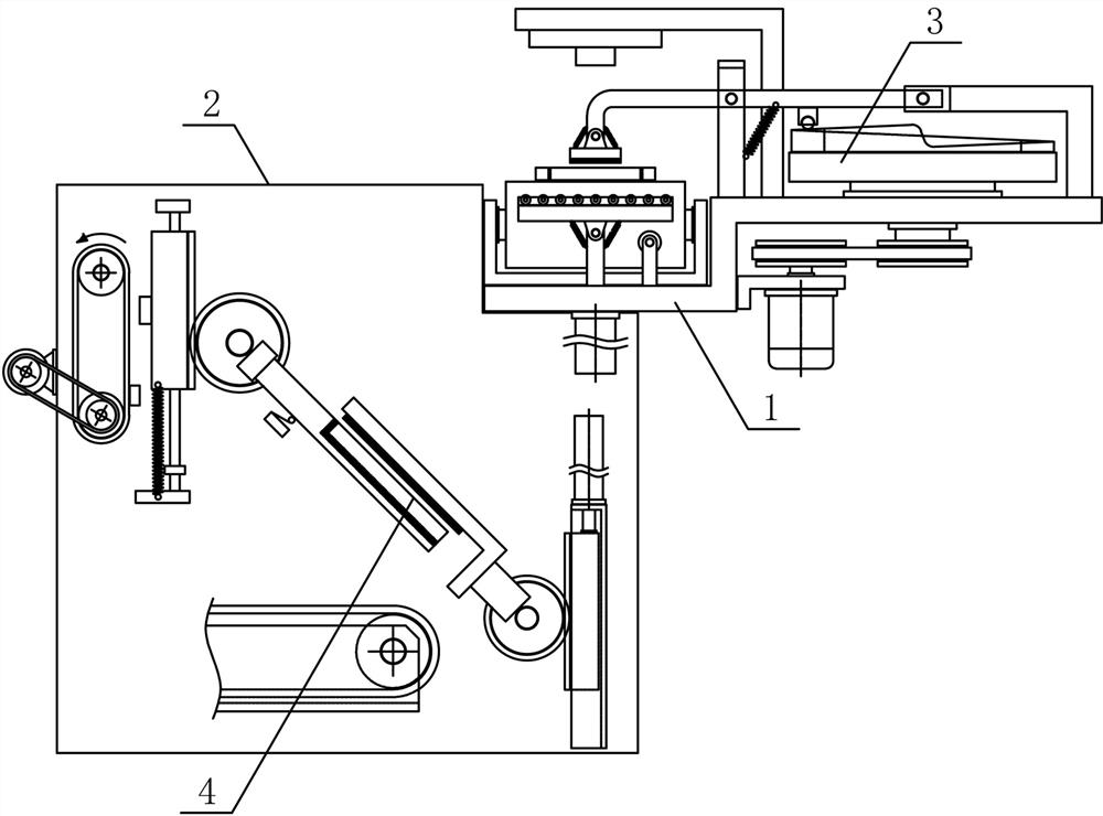
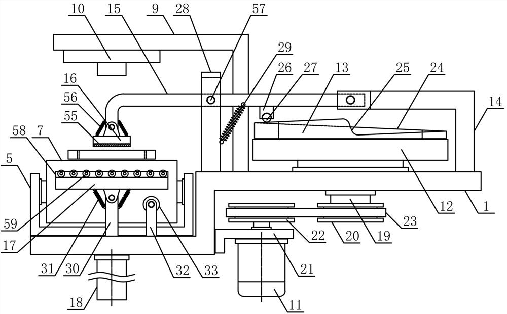
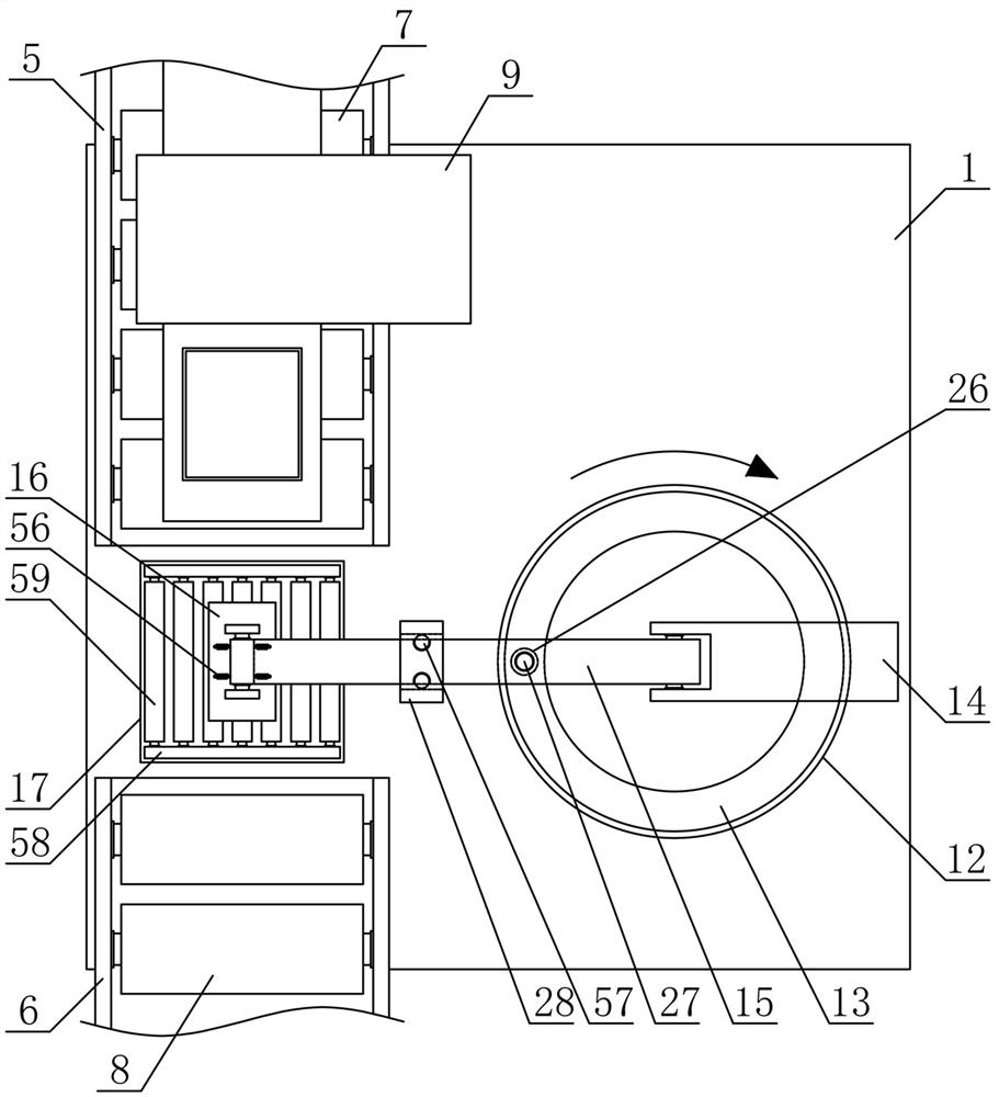

Image

  • Working method of metal plate transferring mechanism
  • Working method of metal plate transferring mechanism
  • Working method of metal plate transferring mechanism

Examples


Embodiment Construction

[0013]In order to further describe the present invention, a specific embodiment of a metal sheet transfer mechanism is further illustrated in connection with the accompanying drawings, and the following examples are not limited to the following examples.

[0014]Such asfigure 1 ,figure 2 withimage 3 As shown, the present invention includes a metal plate portrait mechanism including a machining bracket 1, a shifting bracket 2, a push plate conductive mechanism 3, and a transport transfer mechanism 4, and the processing bracket 1 is fixed to the upper side of the shift bracket 2, The push plate conductive mechanism 3 is disposed on the upper side of the machining bracket 1, and the transport transfer mechanism 4 is vertically disposed on the side of the shifting bracket 2, and the machining bracket 1 is fixed in the horizontal direction, respectively, and the front feed bracket 5 is provided. The subsequent feed bracket 6, the front feed bracket 5 is horizontally rotated in the horizonta...


PUM


Abstract

The invention discloses a working method of a metal plate transferring mechanism, and belongs to the field of profile machining mechanical equipment. A push plate guide mechanism is horizontally arranged on the upper side of a machining support; a transferring mechanism is vertically arranged on one side of a transferring support; a front conveying support and a rear conveying support are horizontally and fixedly arranged at the two ends of one side of the upper portion of the machining support in the horizontal direction; a laser cutting machine is horizontally and fixedly arranged at the position, on one side of the upper portion of the front conveying support, of the machining support; the push plate guide mechanism is horizontally arranged at the position, on one side of the front conveying support and one side of the rear conveying support, of the machining support; a transferring guide plate is fixedly arranged on one side of a transferring gear in the radial direction of the transferring gear; a transferring belt is horizontally arranged on the upper side of a conveying support; and the transferring guide plate is fixedly arranged on one side of a plate containing gear in the radial direction of the plate containing gear. The mechanism is reasonable in structural design, a metal plate obtained through cutting machining can be rapidly and efficiently transferred, the automation degree is high, and the machining and use needs are met.

Description

Technical field[0001]The present invention belongs to the field of profile processing machinery, and more particularly to a working method of a metal sheet transfer mechanism, mainly used in the continuous processing of metal sheets.Background technique[0002]The metal plate refers to a structural sheet having a certain size of a flat rectangular structure made of metal material, and the use of the metal sheet is extremely wide, and the metal sheet can be used in various industrial products according to the size specifications of the metal sheet, mainly including the car. Equipment, financial equipment, communication equipment and cabinet chassis, etc.[0003]During the production and processing of the metal sheet, the metal sheet having a small size specification is mainly made of cutting processing as needed with a large metal sheet having a large size, and the existing metal sheet is difficult to achieve the continuous production of pipelines during the cutting process. The cutting ...

Claims


Application Information

Patent Timeline
Patent Type & Authority Applications(China)
IPC IPC(8): B65G47/82B65G47/92B23K26/70B23K26/38
CPCB23K26/702B23K26/38B65G47/82B65G47/92B65G2201/022
Inventor 黄明珠
Owner 黄明珠
Why Eureka
Eureka Blog
Learn More