Waste heat utilization system of electric heating steam generator
A steam generator and electric heating technology, applied in applications, home appliances, washing devices, etc., can solve problems such as waste of resources, and achieve the effects of saving environmental protection, shortening heating time, and improving utilization rate
- Summary
- Abstract
- Description
- Claims
- Application Information
AI Technical Summary
Problems solved by technology
Method used
Image

Examples
Embodiment 1
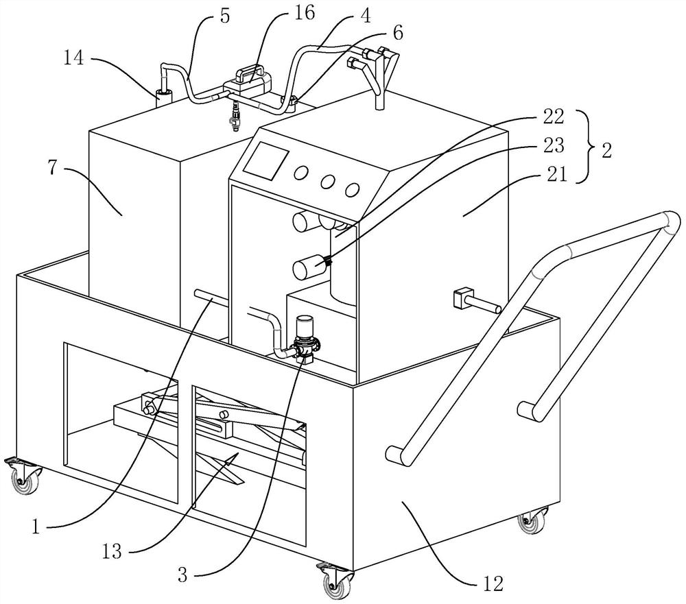
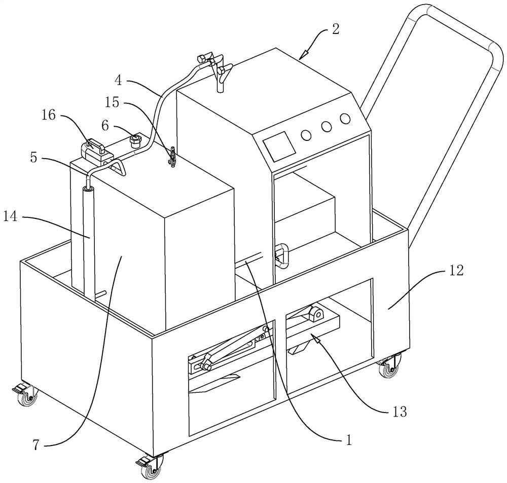
[0038] refer to figure 1 and figure 2 , The waste heat utilization system of the electric heating steam generator is composed of a water supply pipe 1, an electric heating steam generator 2, a first water pump 3, a steam outlet pipe 4, an exhaust pipe 5, an exhaust valve 6 and an insulated water storage tank 7, etc. For the convenience of description, in the figure, the state of the electric heating steam generator 2 and the heat preservation water storage tank 7 in use shall prevail. The surface adjacent to the ground of the electric heating steam generator 2 and the heat preservation water storage tank 7 is the bottom wall, which is opposite to the ground. Face the top wall, and the rest are side walls.
[0039] refer to figure 1 and figure 2 , the electric heating steam generator 2 includes a box body 21, an inner tank 22 and a heater 23, a fixing seat is welded in the box body 21, the inner tank 22 is clamped and fixed on the fixing seat, and the heating end of the he...
Embodiment 2
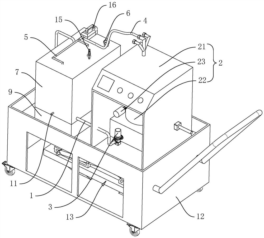
[0049] refer to image 3 with Figure 4 The difference between this embodiment and Embodiment 1 is that it also includes a condensed water tank 9, the condensed water tank 9 is located below the heat preservation water tank, and the condensate water tank 9 communicates with the heat preservation water tank.
[0050] refer to Figure 5 , also includes a heat exchange assembly 8, and the heat exchange assembly 8 is located in the heat preservation water storage tank 7. The heat exchange assembly 8 includes a first condensing coil 81 and a second condensing coil 82, the first condensing coil 81 and the second condensing coil 82 extend upwards and communicate with the first exhaust pipe 5 through a pipe joint, the first The condensing coil 81 and the second condensing coil 82 extend downwards through the bottom wall of the insulated water storage tank 7 and into the condensed water tank 9 .
[0051] Among them, the first condensing coil 81 and the second condensing coil 82 not ...
PUM
 Abstract
Description
Claims
Application Information