Superconducting magnet connecting device and superconducting magnetic levitation vehicle track system

A technology of superconducting magnets and connecting devices, which is applied in the direction of electric vehicles, rails, vehicle parts, etc., and can solve the disadvantages of the dynamic performance and comfort of maglev vehicles, the inability to stably and safely support superconducting magnets, and the inability to elastically hang superconducting magnets and other issues, to achieve the effect of reasonable and ingenious structural design, lower rigidity requirements, and lower quality

Active Publication Date: 2022-07-15
HIWING TECH ACAD OF CASIC
View PDF7 Cites 0 Cited by
  • Summary
  • Abstract
  • Description
  • Claims
  • Application Information

AI Technical Summary

Problems solved by technology

[0005] First, the Dewar outside the superconducting magnet suitable for the whole vehicle is generally 5 to 6 meters long, and a series of springs are arranged at the front and rear ends of the top respectively. The load of the whole vehicle is first transmitted to the outer Dewar of the superconducting magnet, and then Inwardly transmitted to the coil of the superconducting magnet, that is, the outer Dewar of the superconducting magnet bears the concentrated load of the whole vehicle; therefore, the strength and stiffness of the outer Dewar are extremely high, resulting in a large mass of the superconducting magnet, which often occupies the entire suspension frame. 50% or more of the mass, and this part of the mass is the unsprung mass, the increase in mass is extremely detrimental to the dynamic performance of the maglev vehicle and the comfort during normal driving
[0006] Second, the superconducting magnet cannot generate sufficient electromagnetic levitation force and guiding force when running at low speed. At this time, the superconducting magnet needs to be safely supported on the suspension frame when it is supported by the landing gear and guide wheels. The first series of springs in the above patent are Air springs, air springs are basically unable to bear the tension, so the first series of springs cannot elastically hang the superconducting magnet, resulting in the inability to support the superconducting magnet stably and safely when the vehicle is running at low speed; in addition, only relying on rigid brakes to support the superconducting magnet at low speed will Causes excessive vibration, resulting in poor comfort when superconducting electric magnetic levitation vehicles run at low speeds

Method used


Image

  • Superconducting magnet connecting device and superconducting magnetic levitation vehicle track system
  • Superconducting magnet connecting device and superconducting magnetic levitation vehicle track system
  • Superconducting magnet connecting device and superconducting magnetic levitation vehicle track system

Examples


Embodiment 1

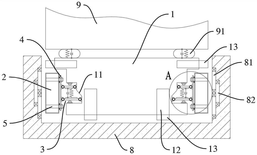
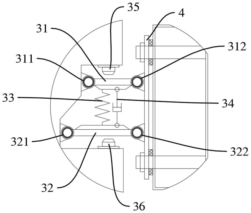
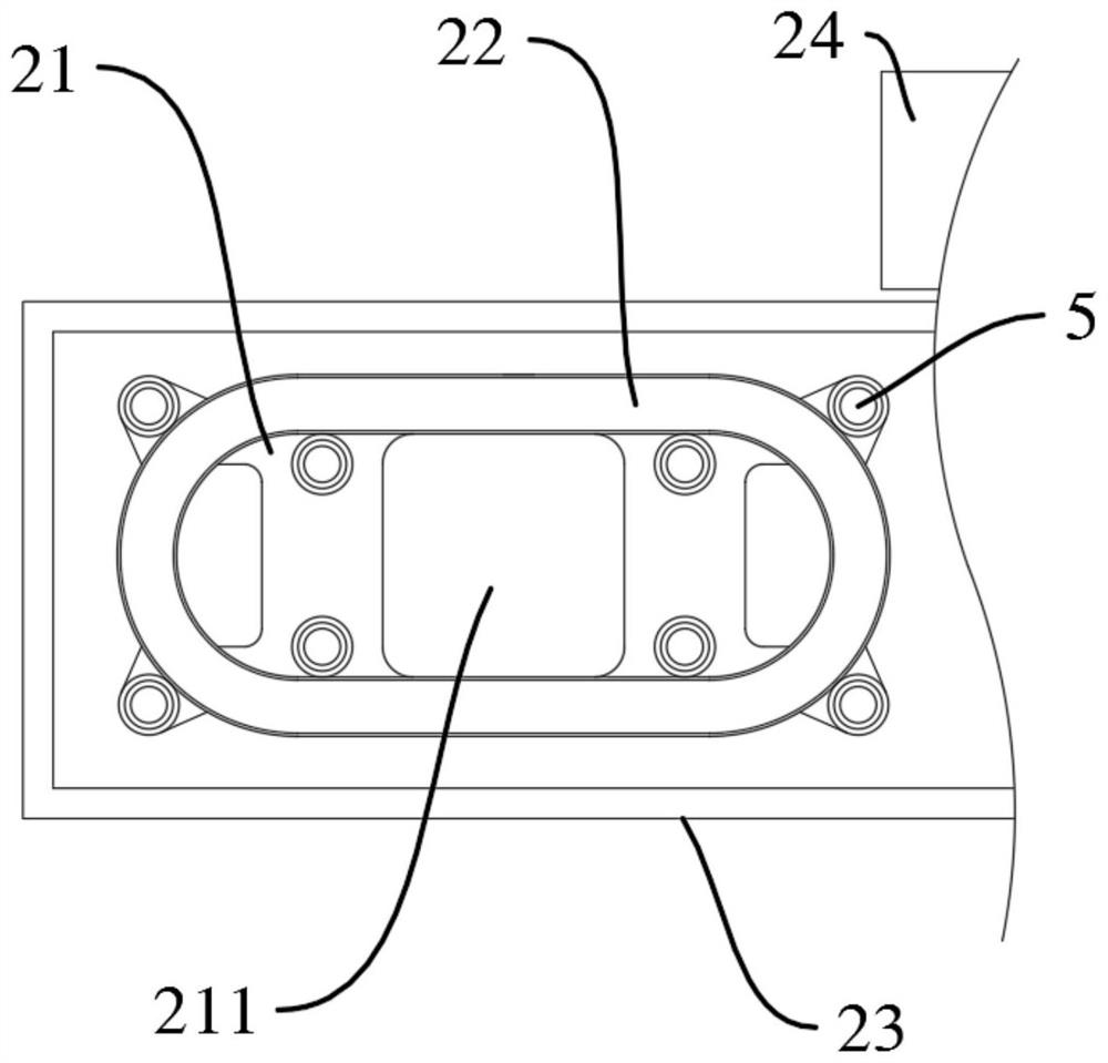
[0028] Example 1, see Figure 1 to Figure 3 , the embodiment of the present invention provides a superconducting magnet connection device, which is suitable for the connection between the suspension frame frame 1 and the superconducting magnet 2, including: a cavity 11, which is arranged on the suspension frame frame 1; Inside the superconducting magnet 2, it is used to connect the inner Dewar 22 that fixes the superconducting magnet 2; the elastic support mechanism 3 is arranged in the cavity 11, and is used to absorb the suspension frame 1 through the cavity The first resultant force applied by 11, and output the second resultant force after the first resultant force is damped; the force transfer member 4 is arranged between the superconducting magnet 2 and the suspension frame frame 1, and is connected with the elastic The support mechanism 3 is connected to transfer the second resultant force output by the elastic support mechanism 3; a plurality of force transmission memb...

Embodiment 2

[0060] Example 2, refer to Figure 1 to Figure 4 , on the basis of Embodiment 1, the elastic support part is replaced by: including a second vibration damping positioning spring 61, which is placed between the upper wall surface of the cavity 11 and the upper cross arm 31, and is connected with the The upper wall of the cavity 11 is connected to the upper cross arm 31 ; the second shock absorber 62 is placed between the upper wall of the cavity 11 and the upper cross arm 31 , and is connected to the upper cross arm 31 of the cavity 11 . The upper wall surface and the upper cross arm 31 are connected; the second low-speed support spring 63 is arranged on the lower wall surface of the cavity 11 corresponding to the lower cross arm 32 .

[0061] Specifically, the upper transverse arm 31 is pushed down by the second vibration damping positioning spring 61 , and the upper transverse arm 31 drives the superconducting magnet 2 to move down until the lower transverse arm 32 is support...

Embodiment 3

[0063] Example 3, refer to Figure 1 to Figure 5 , on the basis of Embodiment 1, the elastic support part is replaced by: including a third vibration damping positioning spring 71, which is placed between the upper end surface of the force transfer member 4 and the suspension frame frame 1, and is connected with the The upper end surface of the force transfer member 4 is connected to the suspension frame frame 1; the third shock absorber 72 is placed between the upper wall surface of the cavity 11 and the upper cross arm 31, and is connected to the cavity The upper wall surface of 11 and the upper cross arm 31 are connected; the third low-speed support spring 73 is arranged on the lower wall surface of the cavity 11 corresponding to the lower cross arm 32 .

[0064] Specifically, the third vibration damping positioning spring 71 pushes the force transfer member 4 to move down, and the force transfer member 4 drives the superconducting magnet 2 , the upper cross arm 31 and the ...


PUM


Abstract

The invention provides a superconducting magnet connecting device and a superconducting dynamic magnetic levitation vehicle track system, wherein the superconducting magnet connecting device comprises: a cavity, which is arranged on a suspension frame; an adiabatic support mechanism is arranged on the superconducting magnet In the body, it is used to connect the inner dewar of the fixed superconducting magnet; the elastic support mechanism is arranged in the cavity, which is used to absorb the first resultant force exerted by the suspension frame through the cavity, and output the second resultant force after the first resultant force is buffered The force transfer member is arranged between the superconducting magnet and the suspension frame frame; a plurality of force transfer members are connected to the adiabatic support mechanism and the force transfer member, and are used to dispersely act on the second resultant force on the adiabatic support mechanism to be distributed to the adiabatic support mechanism. The inner dewar of superconducting magnets. The force transmission path from the superconducting magnet to the suspension frame is simplified, and the problems that the superconducting magnet requires high rigidity and low vehicle running comfort, and the vehicle cannot support the superconducting magnet stably and safely when the vehicle runs at low speed are solved.

Description

technical field [0001] The invention designs the field of superconducting dynamic magnetic levitation traveling mechanisms, in particular to a superconducting magnet connecting device and a superconducting dynamic magnetic levitation vehicle track system. Background technique [0002] The superconducting electric magnetic levitation vehicle (EDS) generally adopts the side wall type suspension. The ground suspension guide coil and the ground propulsion coil are arranged on the two side walls of the U-shaped track, and the superconducting magnets are arranged on both sides of the suspension frame. The magnetic field generated by the ground propulsion coil It acts with the superconducting magnet to drive the vehicle to run, and the magnetic field generated by the superconducting magnet cuts the ground suspension coil to form an induced current and an induced electric field, and relies on the interaction between the induced electric field and the superconducting magnet to achieve...

Claims


Application Information

Patent Timeline
Patent Type & Authority Patents(China)
IPC IPC(8): E01B25/30B60L13/04
CPCE01B25/30E01B25/305B60L13/04
Inventor 武震啸毛凯刘德刚王少聪赵明李萍王亮刘志姜智杰
Owner HIWING TECH ACAD OF CASIC
Why Eureka
Try Eureka