
Automatic focusing method and system based on ultrasonic microscope point focusing transducer

An ultrasonic microscope and auto-focusing technology, which is used in material analysis, instruments, and scientific instruments using sonic/ultrasonic/infrasonic waves. uncertainty and uncertainty, improving focusing speed and accuracy, reducing operational complexity

Active Publication Date: 2021-04-09
UNIVERSITY OF CHINESE ACADEMY OF SCIENCES
View PDF9 Cites 1 Cited by
  • Summary
  • Abstract
  • Description
  • Claims
  • Application Information

AI Technical Summary

Problems solved by technology

[0003] At present, ultrasonic microscopes generally adopt the manual focusing method, which is not only low in precision but also inefficient, especially in the face of highly integrated IC chips, multi-layer thin film materials, etc., manual focusing has greatly reduced the detection efficiency, and it is possible Affect the detection effect
In the process of scanning imaging and non-destructive testing of complex multi-layer structure specimens, especially chips, by using point-focusing transducers, the focusing process of the middle layer requires the operator to have rich working experience and comparative experience. long operating time
This also largely limits the wide application of ultrasound microscopy

Method used


Image

  • Automatic focusing method and system based on ultrasonic microscope point focusing transducer
  • Automatic focusing method and system based on ultrasonic microscope point focusing transducer
  • Automatic focusing method and system based on ultrasonic microscope point focusing transducer

Examples


Embodiment Construction

[0057] The implementation mode of the present invention is illustrated by specific specific examples below, and those who are familiar with this technology can easily understand other advantages and effects of the present invention from the contents disclosed in this description. Obviously, the described embodiments are a part of the present invention. , but not all examples. Based on the embodiments of the present invention, all other embodiments obtained by persons of ordinary skill in the art without making creative efforts belong to the protection scope of the present invention.

[0058] In view of the above problems, the embodiment of the present application provides an autofocus technology based on the ultrasonic microscope point focus transducer, which can effectively solve the problems of slow focusing speed and low precision of the ultrasonic microscope point focus transducer, and improve the performance of the ultrasonic microscope. Imaging quality and NDT efficiency...


PUM


Abstract

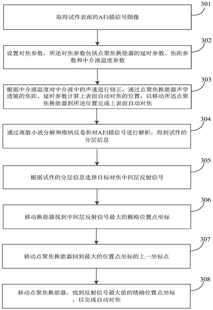
The embodiment of the invention discloses an automatic focusing method and system based on an ultrasonic microscope point focusing transducer. The method comprises the steps of: acquiring an A scanning signal image of the surface of a test piece; setting focusing parameters; correcting the sound velocity in the intermediary liquid according to the temperature of the intermediary liquid, and calculating the automatic focusing position of the upper surface through the focal length, delay and other parameters of the acoustic lens of the point focusing transducer; analyzing the scanning signal A through discrete wavelet decomposition and Wiener deconvolution to obtain layering information of the test piece; selecting a target focusing interlayer reflection signal according to the layering information of the test piece; moving the transducer to find out the coordinate of the approximate position point with the maximum middle layer reflection signal; moving the point focusing transducer back to the previous coordinate point of the maximum position point coordinate; and moving the point focusing transducer to find the accurate position point coordinate of the maximum value of the reflected signal so as to complete automatic focusing. Therefore, the focusing speed and precision of the point focusing transducer of the ultrasonic microscope in the using process are effectively improved.

Description

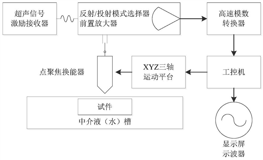
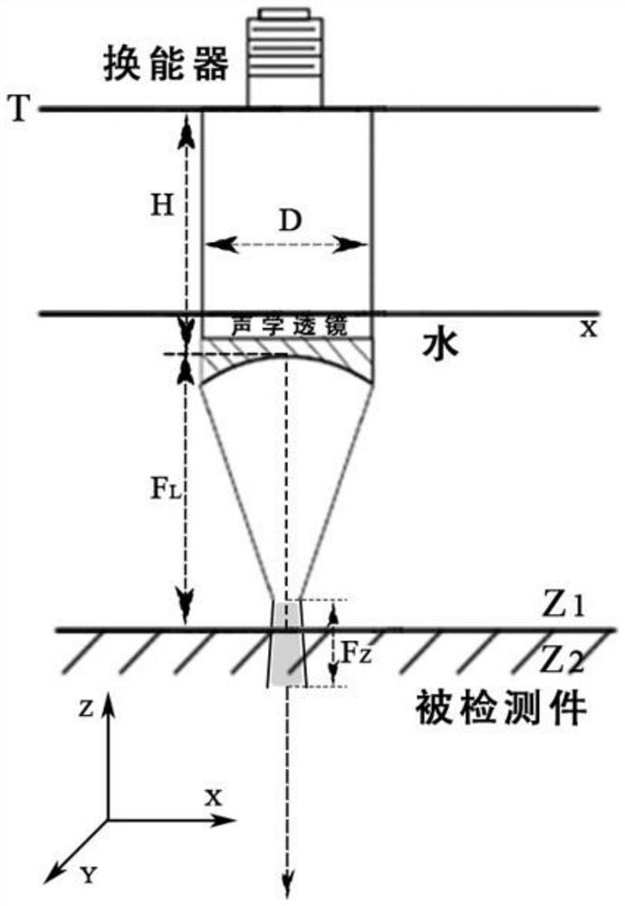
technical field [0001] The embodiment of the present application relates to the field of acoustic technology and non-destructive testing technology, and specifically relates to an autofocus method and system based on an ultrasonic microscope point focusing transducer. Background technique [0002] Ultrasonic microscopes are non-destructive testing and microscopic imaging equipment widely used in high-tech manufacturing industries such as chip manufacturing, biomedicine, and material science. Ultrasound microscope (such as figure 1 Schematic diagram of the ultrasonic microscope) liquid-immersion point-focused ultrasonic transducers are commonly used (such as figure 2 Focusing schematic diagram of the point-focused ultrasonic transducer), the transducer can converge the sound beam at one point, so that the energy concentration in the convergence area is strengthened, and the width of the sound beam becomes smaller, which can meet the detection requirements of high sensitivit...

Claims


Application Information

Patent Timeline
IPC IPC(8): G01N29/26
CPCG01N29/262G01N2291/023
Inventor 梁昊吕科薛健
Owner UNIVERSITY OF CHINESE ACADEMY OF SCIENCES
Learn More