Heat-resistant alloy high-efficiency milling cutter

A technology for milling cutters and heat-resistant alloys, which is applied in milling cutters, manufacturing tools, milling machine equipment, etc., can solve the problems of reduced machining accuracy, low machining efficiency, and low machining life, and achieves improved milling strength and accuracy. Good cooling effect , The effect of long processing life

Pending Publication Date: 2021-04-13
WUXI GUOHONG MEASURING & CUTTING TOOLS
View PDF0 Cites 0 Cited by
  • Summary
  • Abstract
  • Description
  • Claims
  • Application Information

AI Technical Summary

Problems solved by technology

[0004] 1. During the blisk machining process, the surface structure of the blade is complex, the direction of the tool axis is constantly changing, the wear degree of the ball cutter is large during the machining process, and the machining life is low;
[0005] 2. Ordinary ball cutters have poor chip removal ability, easy to break the cutter, and low processing efficiency;
[0006] 3. When the ball cutter is processing the surface of the blisk, the rebound of the blisk surface to the ball cutter will increase, so the area in contact with the ball cutter will increase, and the machining accuracy will decrease.

Method used


Image

  • Heat-resistant alloy high-efficiency milling cutter
  • Heat-resistant alloy high-efficiency milling cutter
  • Heat-resistant alloy high-efficiency milling cutter

Examples


Embodiment 1

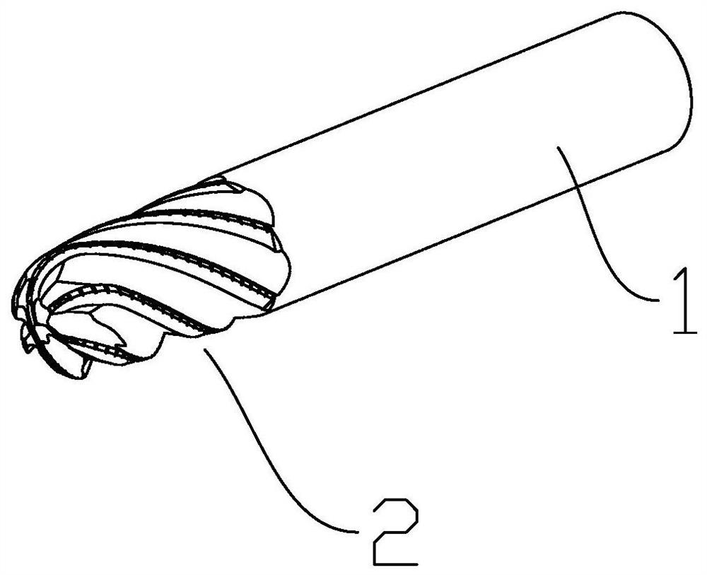
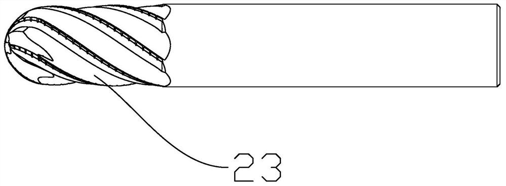
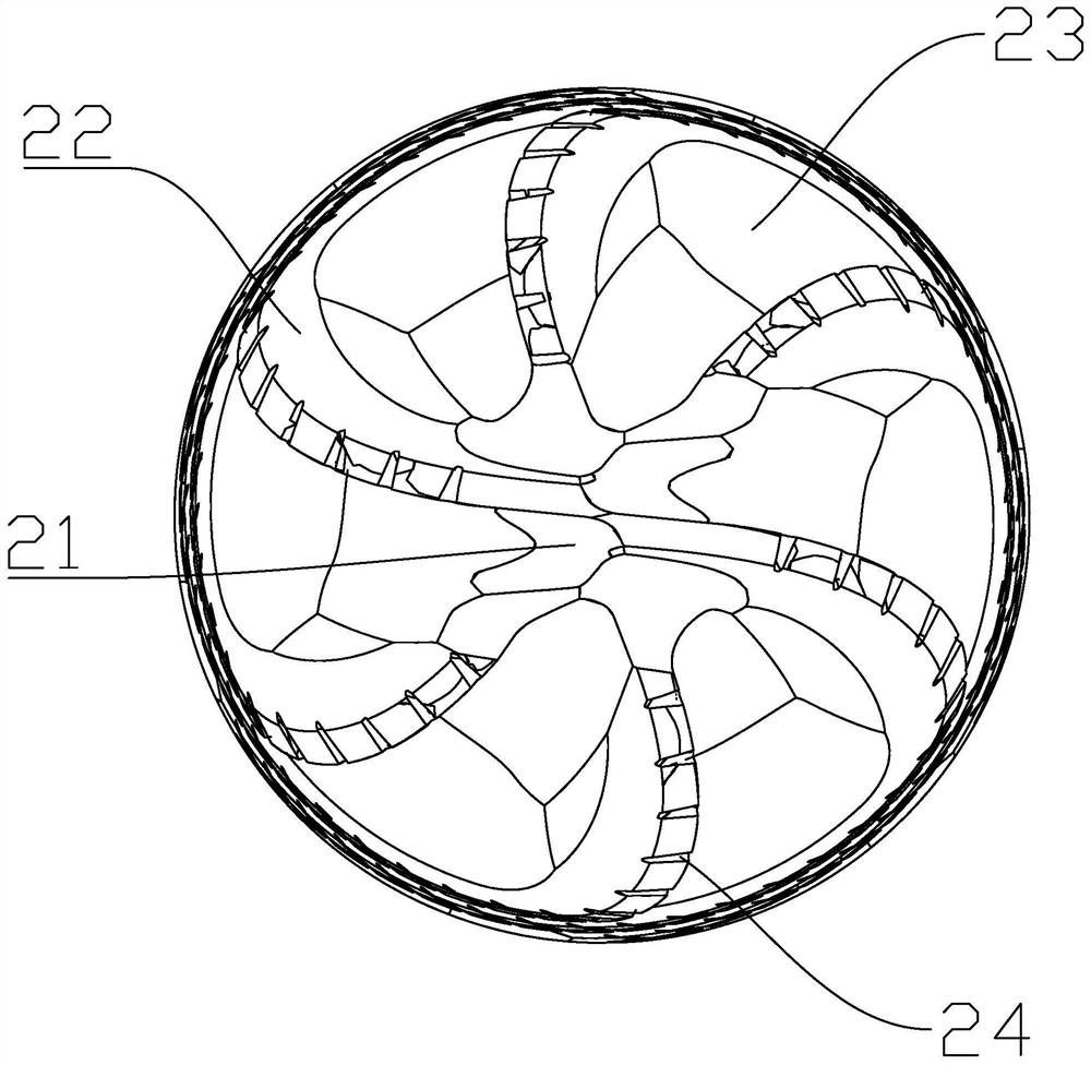
[0021] Embodiment 1, a heat-resistant alloy high-efficiency milling cutter, including a cutter bar, is characterized in that: one end of the cutter bar is formed with a cutter head, and the cutter head is formed with a central boss, and is provided with a cutting edge and a chip removal groove , the central boss is fixedly connected to the center of the cutter bar, the central boss is coaxially arranged with the cutter bar, and the cutting edges include at least four, and the cutting edges are evenly distributed on the side circumference of the central boss and are formed by the The central boss is arranged in the center circle, the chip removal groove is set between the two cutting edges, the top of the central boss is the base surface, and every two cutting edges symmetrical to the central axis of the central boss on the base surface are S shape, the cutting edge and chip flute extend to the side of the tool holder in the same helical direction, and the cutting edge and the t...


PUM


Abstract

The invention discloses a heat-resistant alloy high-efficiency milling cutter and solves the problems of easy chip removal and cutter breaking, short service life, low processing efficiency and the like of a conventional ball cutter during rough machining of a blade disc. According to the technical scheme, the heat-resistant alloy high-efficiency milling cutter is characterized by comprising a cutter bar, wherein a cutter head is formed at one end of the cutter bar; a central boss is formed on the cutter head; cutting edges and a chip groove are formed in the cutter head; the central boss is fixedly connected with the center of the cutter bar; the central boss and the cutter bar are coaxially arranged; the number of the cutting edges is at least four; the cutting edges are evenly distributed on the side periphery of the central boss and circumferentially arranged with the central boss as the center; the chip groove is formed between the two cutting edges; the top of the central boss serves as a base face; every two cutting edges, symmetrical about the central axis of the central boss, on the base face are in an S shape; the cutting edges and the chip groove extend to the side body of the cutter bar in the same spiral direction; and the cutting edges and the cutter bar are connected into a whole.

Description

technical field [0001] The invention relates to the technical field of cutters, more specifically, it relates to a heat-resistant alloy high-efficiency milling cutter. Background technique [0002] In the rough machining of titanium alloy blisks in the field of aero-engines, the blisks are generally made of titanium alloys or high-temperature alloys, which are directly processed through traditional processing, so there are a large number of rough machining links in the early stage, and the overall structure of the blisks is complex. , The blade has a large twist, and the ball cutter is often used for side milling during processing. [0003] However, ordinary ball cutters have the following problems when processing blisks: [0004] 1. During the blisk machining process, the surface structure of the blade is complex, the direction of the tool axis is constantly changing, the wear degree of the ball cutter is large during the machining process, and the machining life is low; ...

Claims


Application Information

Patent Timeline
Patent Type & Authority Applications(China)
IPC IPC(8): B23C5/10B23C5/28
CPCB23C5/10B23C5/28
Inventor 张峰熊焰王必永吴桂平于忠光韩占龙卞小锋王磊
Owner WUXI GUOHONG MEASURING & CUTTING TOOLS
Why Eureka
Try Eureka