
Circular cutting auxiliary device of angle grinder

An auxiliary device and circular cutting technology, which is applied in the direction of grinding machines, portable grinding machines, grinding/polishing equipment, etc., can solve problems such as difficulty in ensuring the straightness and angle of chamfering, rough incision, shaking of cutting machine and plate, etc., and achieve improvement Accuracy and practicability, precise circle cutting standard, precise cutting and positioning effect

Inactive Publication Date: 2021-04-13
无锡博楷电动工具制造有限公司
View PDF0 Cites 0 Cited by
  • Summary
  • Abstract
  • Description
  • Claims
  • Application Information

AI Technical Summary

Problems solved by technology

[0003] However, there are still some shortcomings in its actual use. For example, at present, when the building decoration industry chamfers ceramic tiles and stones, it usually supports the plate with one hand and holds the cutting machine with the other. The processing quality depends entirely on the operator's technical level. This processing method is easy to cause the cutting machine and the plate to shake, it is difficult to ensure the straightness and angle of the chamfer, the incision is rough, the trimming edge is not straight, and the cutting quality is poor. It often requires multiple corrections to meet the requirements, which is very time-consuming and efficient. Low cost, low man-hour cost, and at the same time, in order to improve the cutting accuracy during the cutting process, it is necessary to stop the cutting process many times for measurement and calibration, which greatly reduces the cutting efficiency

Method used


Image

  • Circular cutting auxiliary device of angle grinder
  • Circular cutting auxiliary device of angle grinder
  • Circular cutting auxiliary device of angle grinder

Examples


Embodiment Construction

[0022] The following will clearly and completely describe the technical solutions in the embodiments of the present invention with reference to the accompanying drawings in the embodiments of the present invention. Obviously, the described embodiments are only some, not all, embodiments of the present invention. Based on the embodiments of the present invention, all other embodiments obtained by persons of ordinary skill in the art without making creative efforts belong to the protection scope of the present invention.

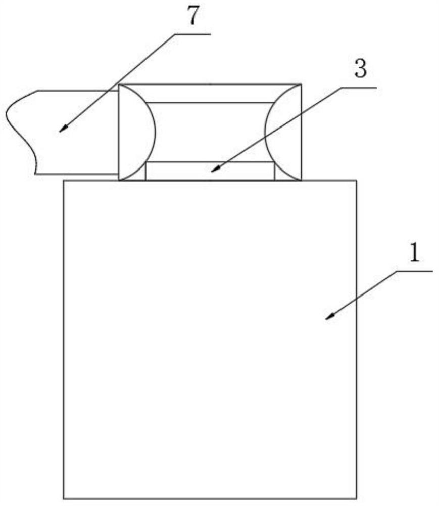
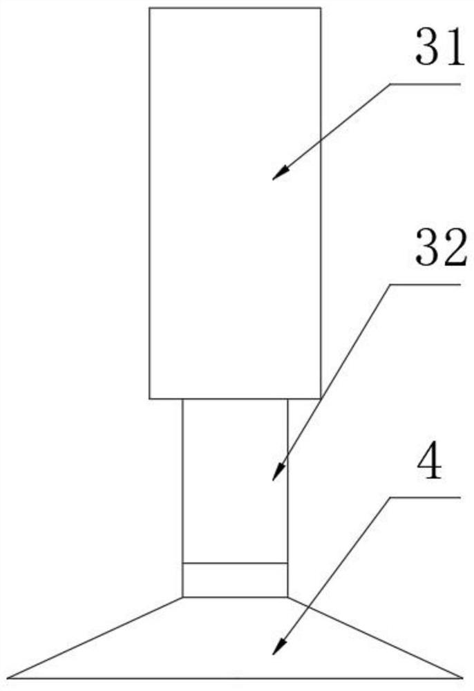
[0023] as attached Figure 1-5 A circular cutting auxiliary device for an angle grinder is shown, which includes a soft airtight cylinder 1, a suction cavity 2 is provided inside the soft airtight cylinder 1, and a positioning connecting column 3 is fixedly installed at the center of the suction cavity 2 , the end of the positioning connecting column 3 is fixedly installed with a positioning suction cup 4, the inside of the suction cavity 2 is fixedly installe...


PUM


Abstract

The invention discloses a circular cutting auxiliary device of an angle grinder, and particularly relates to the technical field of circular cutting auxiliary devices of angle grinders. The circle cutting auxiliary device comprises a soft airtight cylinder, wherein a suction cavity is formed in the soft airtight cylinder, a positioning connecting column is fixedly installed in the center of the suction cavity, a positioning sucker is fixedly installed at the end of the positioning connecting column, an elastic separation assembly and a check exhaust valve are fixedly installed in the suction cavity, and a first positioning measurement supporting arm is movably installed outside the soft airtight cylinder. By arranging the soft airtight cylinder, in the working process of the device, point finding and fixing are conducted through the positioning connecting column and the positioning sucker, then the soft airtight cylinder is extruded through external force, internal air of the soft airtight cylinder is exhausted through the check exhaust valve, and the soft airtight cylinder and a cutting machining raw material are tightly attached and fixed, so that a positioning fulcrum is determined for the cutting work of the angle grinder, the cutting positioning accuracy is ensured, and the problem that the machining amount is not qualified due to inaccurate manual positioning is solved.

Description

technical field [0001] The invention relates to the technical field of an angle grinder circular cutting auxiliary device, more specifically, the invention relates to an angle grinder circular cutting auxiliary device. Background technique [0002] Angle grinder, also known as grinder or disc grinder, is a kind of abrasive tool used for cutting and grinding FRP. Angle grinder is a portable electric tool that uses FRP cutting and grinding. It is mainly used for cutting, grinding and grinding. Brushing metal and stone etc. [0003] However, there are still some shortcomings in its actual use. For example, at present, when the building decoration industry chamfers ceramic tiles and stones, it usually supports the plate with one hand and holds the cutting machine with the other. The processing quality depends entirely on the operator's technical level. This processing method is easy to cause the cutting machine and the plate to shake, it is difficult to ensure the straightness ...

Claims


Application Information

Patent Timeline
IPC IPC(8): B24B23/02B24B23/00
CPCB24B23/005B24B23/028
Inventor 詹祥感
Owner 无锡博楷电动工具制造有限公司
Learn More