
High-precision bearing steel ball polishing production process for field of 5G or 6G communication

A bearing steel ball and production process technology, used in grinding/polishing equipment, machine tools with surface polishing, machine tools suitable for grinding workpiece edges, etc., can solve the problem of small improvement, poor polishing effect, and easy to appear Dead angle balls and other problems, to avoid dead angle balls, improve polishing effect, and achieve good polishing effect

Pending Publication Date: 2021-04-13
JIANGSU LIXING GENERAL STEEL BALL
View PDF0 Cites 1 Cited by
  • Summary
  • Abstract
  • Description
  • Claims
  • Application Information

AI Technical Summary

Problems solved by technology

The above-mentioned polishing method only uses steel balls to collide with each other to achieve polishing, and the polishing effect is not very good. In order to improve the polishing effect, different amounts of iron will be added to the polishing barrel. The collision block, so that the steel ball will hit the iron collision block when it is in circulation. However, although such a method can improve the polishing effect, the improvement is relatively small, and in this way, it is installed When bumping the block, the bumping block is usually fixed in the polishing barrel by bolts. This method needs to drill threaded holes in the polishing barrel in advance. In addition, due to the addition of the bumping block, the phenomenon of dead corner balls is more likely to occur. Especially when processing steel balls with smaller sizes, dead corner balls are more likely to occur

Method used


Image

  • High-precision bearing steel ball polishing production process for field of 5G or 6G communication
  • High-precision bearing steel ball polishing production process for field of 5G or 6G communication
  • High-precision bearing steel ball polishing production process for field of 5G or 6G communication

Examples


Embodiment Construction

[0025] The following embodiments can make those skilled in the art understand the present invention more comprehensively, but do not limit the present invention to the scope of the described embodiments.

[0026] The polishing production process of high-precision bearing steel balls for the 5G or 6G communication field of the present invention includes the following steps

[0027] The first step cleaning: First, put the steel balls into the special cleaning equipment in the shutdown state.

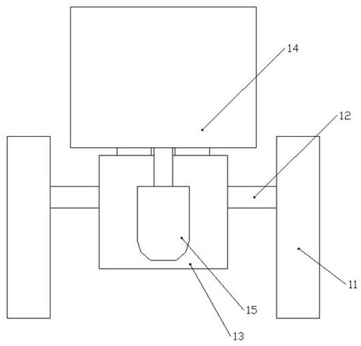
[0028] like figure 1 It can be seen from the schematic diagram shown that the special cleaning equipment includes a pair of cleaning seats 11 distributed in parallel, and a horizontally arranged cleaning rotary rod 12 is connected between the two cleaning seats 11. Both sides of the cleaning rotary rod 12 pass through the bearing and the bearing. The matching seat is installed on the cleaning seat 11, thereby realizing the rolling cooperation between the cleaning rotary rod 12 and the cle...


PUM


Abstract

The invention relates to a high-precision bearing steel ball polishing production process for the field of 5G or 6G communication. The process comprises the following steps that firstly, a steel ball is put into special cleaning equipment in a shutdown state, and the steel ball is cleaned by using water, magnesium oxide and sodium carbonate; a sodium oleate soap water solution is selected to conduct boiling treatment on the cleaned steel ball; special polishing equipment is cleaned and detected, cloth strips are put into an iron polishing barrel and properly scattered, and then the steel ball boiled by the sodium oleate soap water solution is put into the iron polishing barrel to be polished and blow-dried; and it is ensured that no dead angle ball exists in the iron polishing barrel and a screening table through inspection, and the polished steel ball must ensure that the surface is bright, clean, free of mist and free of dirt attachment. The process has the advantages that through cooperation of the special cleaning equipment and the special polishing equipment and design of parameters such as the cleaning time, the boiling temperature and the polishing time, the surface of the steel ball can be cleaned more sufficiently before polishing, and the polishing effect is better during polishing.

Description

technical field [0001] The invention relates to the field of steel ball production, in particular to a polishing production process for high-precision bearing steel balls used in the 5G or 6G communication field. Background technique [0002] In the manufacturing process of steel balls for wind power bearings, it usually needs to go through several major processes such as cold heading, heat treatment, hard grinding, preliminary grinding, polishing, strengthening, fine grinding and cleaning. In the polishing process, due to the high labor intensity of wind power ball polishing, the relative noise of the production environment where equipment and personnel are located is relatively large, and it is difficult to grasp the final quality during the production process. Because the polishing process is easy to get out of control, the steel ball is often not polished due to insufficient polishing time, or the surface of the steel ball is scratched and scratched due to too long polis...

Claims


Application Information

Patent Timeline
IPC IPC(8): B24B31/03B24B31/12B24B31/16B08B3/10B08B13/00C23G1/19
CPCB24B31/03B24B31/12B24B31/16B08B3/10B08B13/00C23G1/19
Inventor 王嵘赵高明何海航沙小建
Owner JIANGSU LIXING GENERAL STEEL BALL
Learn More