Improving method of salt-fog tests on broken section of iron pieces

A technology of salt spray test and iron parts, which is applied in the direction of liquid chemical plating, superimposed layer plating, coating, etc., can solve the problems of corrosion and reduce the salt spray test performance of iron products, so as to simplify the process and improve Salt spray test performance, effect of improving nickel plating quality

Pending Publication Date: 2021-04-13
CHENGDU HOMIN TECH
View PDF7 Cites 0 Cited by
  • Summary
  • Abstract
  • Description
  • Claims
  • Application Information

AI Technical Summary

Problems solved by technology

[0003] After the salt spray test of the iron products, it was found that the iron products rusted quickly at the broken section (2). The main reason for the rapid rust was that there were multiple grooves (3) at the broken section (2). The groove (3) has a certain depth, and when electroplating is performed, the current cannot penetrate to the depth of the groove (3), which leads to the plating of the electroplated nickel layer (4) on the upper half of the side wall of the groove (3). , while there is no electroplated nickel layer on the side wall of the lower half of the trench (3) such as image 3 As shown, the iron material in the groove (3) is finally exposed to the outside, which leads to rapid corrosion there; when electroless plating is performed, because the groove (3) has a certain depth, and in the groove (3) 3) Bubbles are formed at the opening of the trench (3), resulting in the inability of the nickel plating solution to flow in the trench (3), which in turn causes the upper half of the trench (3) to be plated with an electroless nickel layer, while the lower part of the trench (3) Half of the side wall is not plated with chemical nickel layer, which eventually causes the iron material in the groove (3) to be completely exposed to the outside, which leads to rapid corrosion there, thereby reducing the salt spray test performance of the iron product

Method used


Image

  • Improving method of salt-fog tests on broken section of iron pieces
  • Improving method of salt-fog tests on broken section of iron pieces
  • Improving method of salt-fog tests on broken section of iron pieces

Examples


Embodiment Construction

[0023] The present invention will be further described below in conjunction with accompanying drawing, protection scope of the present invention is not limited to the following:

[0024] A salt spray test lifting method for a section of an iron piece comprises the following steps:

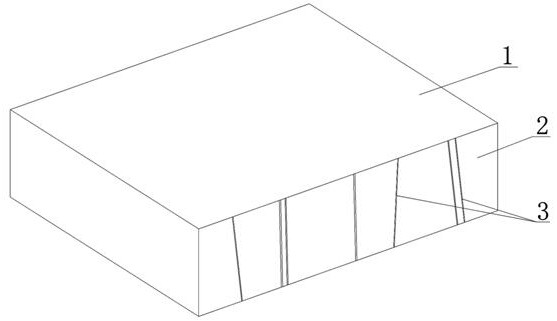
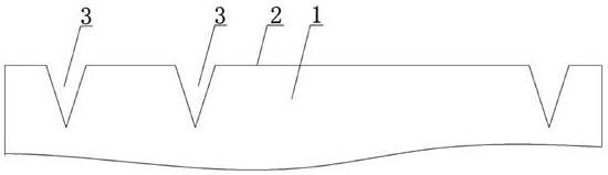
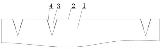
[0025] S1, the grinding process of the iron piece: the broken section 2 of the iron piece 1 is rolled by rolling to reduce the height of the groove 3 on the broken section 2;

[0026] S2, the degreasing process of the iron piece: the iron piece 1 is immersed in the lye, and the ultrasonic wave is passed into the lye, and under the joint action of the lye and the ultrasonic wave, the oil stain attached to the surface of the iron piece 1 is removed. After degreasing for a period of time, the degreasing of iron parts can be realized;

[0027] S3, taking out the degreased iron piece 1 from the alkali washing tank, and washing away the lye on the surface of the iron piece 1 with clear water;

[0028] ...


PUM


Abstract

The invention discloses an improving method of salt-fog tests on broken section of iron pieces. The method comprises the following steps: S1, a step of removing oil on the iron pieces; S3, a step of activating the iron pieces; S5, a step of polishing the iron pieces; S6, a step of electroplating the iron pieces; S7, a step of performing chemical plating on the iron pieces; and S8, processing a protective agent of the iron piece products. The method disclosed by the invention has the beneficial effects that the process is simplified, the salt-fog resistance test performance of the iron piece products are improved, and the nickle-plating quality of the iron piece products is improved.

Description

technical field [0001] The invention relates to a lifting method for a salt spray test on a broken section of an iron piece. Background technique [0002] After the iron piece is punched and formed by the stamping die, multiple grooves (3) are formed on the broken section (2) of the iron piece (1), such as Figure 1~2 The schematic diagram of the structure of the iron part after punching is shown, and the reason for the formation of the groove (3) is the punching force between the punch and the iron part (1). The process requires electroplating and electroless plating of the iron piece (1) to form a layer of nickel plating on the surface of the iron piece (1). After the nickel coating, the iron piece product is obtained, and the iron piece product is subjected to a salt spray test. . Among them, the process of plating the nickel layer is to firstly immerse the iron piece (1) in the electroplating solution to form a layer of electroplated nickel layer on the surface of the i...

Claims


Application Information

Patent Timeline
Patent Type & Authority Applications(China)
IPC IPC(8): C25D5/36C25D5/20C23C18/36C23C28/02
CPCC25D5/36C25D5/20C23C18/36C23C18/1653C23C18/1666C23C28/023
Inventor 黄皓肖学军朱万宇赵景勋吴传伟饶轩
Owner CHENGDU HOMIN TECH
Why Eureka
Try Eureka